Chapter 1- General Description 7400 Series UPS User Manual
Operator Control Panel Single Module and One plus One Systems
6310018a.02.doc
1-12
Issue 2
(02/98)
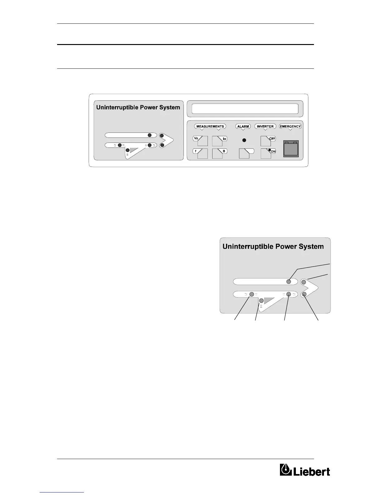
1.4 Operator Control Panel
The operator control panel is divided into three functional areas; ‘mimic
indications’, ‘control switches’, and ‘LCD display panel’.
Six leds are mounted on a single line diagram to represent the various
UPS power paths. These leds, which
are annotated in figure 1-8, show the current UPS operational status and
should be interpreted as detailed below.
LS1 - Input supply OK / Rectifier operative:
This led illuminates when the
input isolator (I1) is closed, the
input supply is within 20% of
nominal voltage, and the
rectifier is operative.
LS2 - Battery volts OK: This
led illuminates when the
battery circuit breaker is closed
and the battery voltage is
within the UPS operating range
(320V - 490V nominal).
LS3 - bypass supply OK: This
led illuminates when the static
bypass supply is within ±10%
of its nominal voltage.
LS4 - Inverter output OK:
This led illuminates when the
inverter is operating and its output is within a preset (±10%) acceptable
voltage window.
LS5 - Load on bypass
This led illuminates when the output isolator is closed and the load is
connected to the bypass supply via the static switch.
LS6 - Load on inverter:
This led illuminates when the output isolator is closed and the load is
connected to the inverter via the static switch.
Figure 1-1 . Operator control panel
1.4.1 Mimic indications
LS3
LS5
LS1 LS2 LS4 LS6
Figure 1-1 . Mimic panel
 Loading...