Chapter 3 - Installation Procedure 7400 Series UPS User Manual
Battery Installation Single Module and One plus One Systems
6310018a.02.doc
3-16
Issue 2
(02/98)
3.4 Connecting the UPS power cables
WARNING
Before cabling-up the UPS, ensure that you are aware of the location and operation of
the external isolators that connect the UPS input/bypass supply to the mains
distribution panel.
Check that these supplies are electrically isolated, and post any necessary warning signs
to prevent their inadvertent operation.
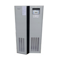
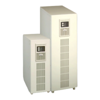
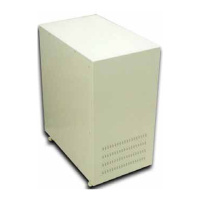
Cables can enter the smaller UPS modules and battery cabinet either
from below or through either side. Side entry is made possible by
removing blanking pieces fitted in the side ventilation grills to reveal the
cable entry holes. This cable entry method allows the equipment to be
positioned on a solid floor without the need for cable trenching and also
allows cables to pass from one module to the other when positioned side-
by-side.
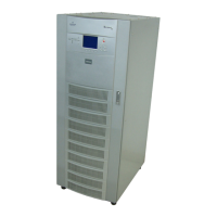
On units up to 200kVA normal cable entry is from the bottom, however,
if top entry is necessary, the optional top entry kit Pt.No. 2174011 Vfor
80 and 120kVA or Pt. No. 2174033 R for 200kVA is required. On the
300/400kVA unit cable entry is from the bottom or top of the unit.
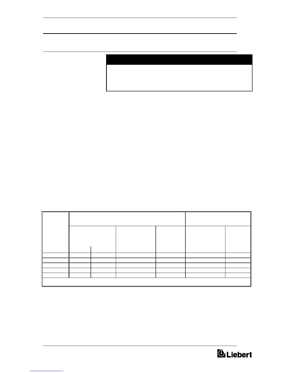
The maximum current ratings for the power cables are given in table 3-1.
The neutral cable (bypass and output) should be sized at up to 1.5 times
the phase current to take into account the possible presence of 3rd
armonic currents due to single phase "computer loads".
In a one-plus-one Non-Redundant system, the lenght of the cables on the
Bypass line of the two UPS’s should be equal (+/- 20%) to ensure the
balance of the currents, when the load is supplied by the mains.
UPS
RATING
NOMINAL CURRENT (Amps) CABLE CONNECTION
MAXIMUM SIZE
(kVA)
Input Mains
(with full battery recharge)
380V
Bypass/output
380V
Battery
(at low battery
disconnect)
Input/output
Cable
Terminations
Battery
Termin-
ations
6 Pulse 12 Pulse U - V - W - N +ve & -ve
80 167 158 121 216 Secure with M8 Bolt M8 Bolt
120 251 237 182 322 Secure with M10 Bolt M10 Bolt
200 412 390 304 534 Secure with M10 Bolt M10 Bolt
300 609 579 442 791 Secure with M12 Bolt M12 Bolt
400 808 769 608 1053 Secure with M12 Bolt M12 Bolt
Table 3-1 - Nominal current for power cables
When sizing battery cables, a maximum volt drop of 3V d.c. is
permissible at the urrent ratings given in table 3-1.
3.4.1 Cable entry
3.4.2 Cable rating



 To Next Page