Chapter 1- General Description 7400 Series UPS User Manual
One plus One System Single Module and One plus One Systems
6310018a.02.doc
1-10
Issue 2
(02/98)
The illustration in figure 1-5 shows a dedicated battery installation for each
module; however, it is possible to fit an option kit which allows the two
modules in a one-plus-one system to share a common battery. Such an
installation is shown in figure 1-6 overleaf.
Note: the "Common battery" configuration is possible with 6 pulse
rectifiers only, not with 12 pulse rectifiers.
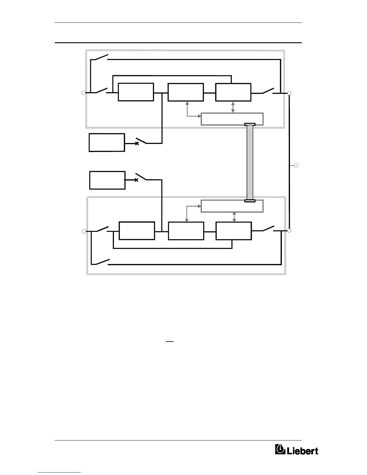
1+1 Parallel Control
Mains
Supply
Mains
Supply
RECTIFIER
STATIC
SWITCH
BATTERY
INVERTER
UPS
Output
Supply
1+1 Parallel Control
RECTIFIER
STATIC
SWITCH
BATTERY
INVERTER
Figure 1-1 . Parallel control in a one-plus-one system
1.3.3 Common battery
 Loading...