7400 Series UPS User Manual Chapter 3 - Installation Procedure
Single Module and One plus One Systems Battery Installation
6310018a.02.doc
3-31
Issue 2
(02/98) LCA 10/01
On initial installation or on change of the battery, it is necessary to enter the battery
nominal capacity data into the system. This allows the front panel to display the
battery state either as a percentage of charge with the input a.c. power supply present
or as the time remaining on battery with the a.c. power supply absent. The battery
circuit breaker must be closed during this procedure.
To initialise the system and insert the nominal battery capacity, press push buttom
‘B’ then carry out the following procedure:
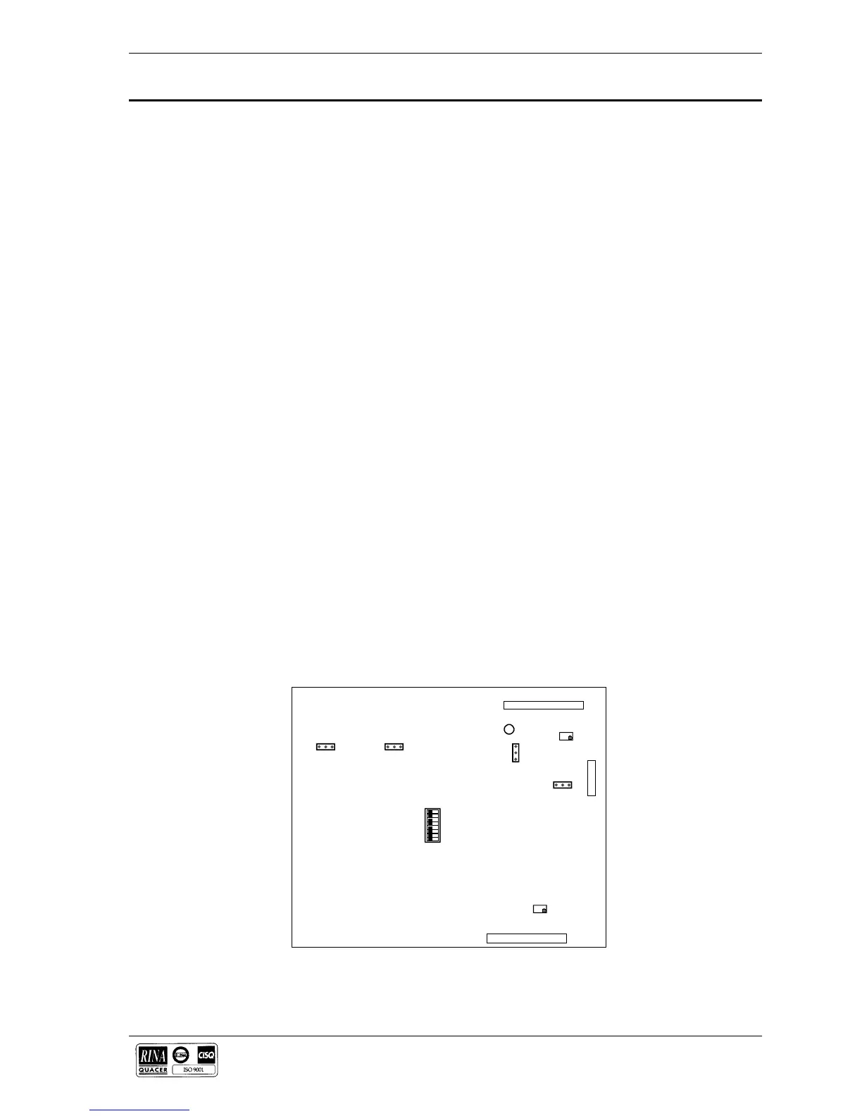
1. On the PCB 4550001 B move the link on SH7 to position on pins 2-3.
2. On the display panel press push buttons ‘f’, ‘B’ and ((*)).
3. Check the display reads:
‘PHASE CALIBRATION’ FREQUENCY: XX,X
4. Press the ((*)) push-button twice and the display will show:-
BATTERY (AH) = NEW VALUE
5. Using the keys: Vo(forward 1), I (forward 10), f (back 1) and B (back 10),
insert the nominal value for the capacity of the installed battery, when
completed press the ((*)) key again.
6. Repeat step 3 and check that the new value for the battery capacity is displayed.
BATTERY (AH) = (new inserted value)
7. On conclusion of the above procedure reposition the link on SH7 to pins 1-2.
8. On the display panel press the keys ‘f’, ‘B’ and ((*)).
9. The display should revert to the default screen
UPS BIOS VERSION 2.1 1-7-1995
The unit has now been restored to normal.
Note: It is necessary to ensure that the reading on the display panel shows B =
100% both on initial installation and on change of battery. This is to ensure that the
measurement reading and subsequent readings are correct.
3.5.3 Battery Display
Initialisation
13
13
13
13
LED 1
SH7
SH1
SH4
SH9
I1
TM1
TM2
CN3
CN4
CN2
Figure 3-1 . SH7 location on Microprocessor PCB