7400 Series UPS User Manual Chapter 4 - Optional equipment
Single Module and One plus One Systems Option Board Kit (Part no. 77000005)
6310018a.02.doc
4-25
Issue 2
(02/98) LCA 10/01
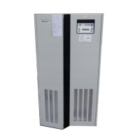
4.9 Pulse Option
The 12 pulse option for the series 7400 UPS is normally factory fitted.
The power and control cable connections for all units are identical to
those given in chapter 3 of this manual. The 300/400 kVA units have the
option fitted into the existing cabinet. However, for 80, 120 and 200
kVA units with part numbers as indicated in the front of this manual, the
option can be fitted on site by a Liebert certified service engineer. The
option is fitted into a purpose designed cabinet that when bolted to the
side of the UPS cabinet extends the system width by 400mm. As with all
series 7400 bolt-on options, the mechanical connection is achieved by
removing the UPS cabinet side panel; the additional cabinet is then
bolted on to the UPS cabinet at the four corners; the side panel removed
from the UPS cabinet is then fitted to the additional cabinet side wall to
complete the system.
For electrical connection of the 12 pulse option part no. 53320001 Z for
80 kVA unit 5332002 A for the 120 kVA unit and 5332004 C for the
200 kVA refer to figures 4-14 and 4-15 and the following instructions.
The details given in figure 4-15 refer to the 80kVA unit. The 120kVA
and 200 kVA units are identical except for the following identification
numbers:
80kVA 120kVA 200kVA
Connector ident CN3 CN4 CN4
Extractor fan VL8 VL10 VL12
WARNING
BEFORE STARTING INSTALLATION OF THIS OPTION ENSURE ALL EXTERNAL
ELECTRICAL POWER SUPPLIES ARE SWITCHED OFF AND MADE SAFE.
DISPLAY THE RELEVANT NOTICES. ENSURE THE BATTERIES ARE ISOLATED
FROM THE UPS. CARRY OUT VOLTAGE CHECKS ON ALL INPUT, OUTPUT AND
BATTERY CONNECTIONS..
1. Gain access to UPS interior, open upper hinged panel. Remove the
bus bar +ve and -ve connection links from between the rectifier
output and the d.c. bus bar.
2. Connect cable 88 from the option cabinet TC4 to the UPS rectifier
output +ve bus bar.
3. Connect cable 89 from the option cabinet L2 (term A1) to the UPS
rectifier output -ve bus bar.
4. Connect cable 49 from the option cabinet L2 (term B) to the UPS
d.c. bus bar +ve connection.
5. Connect cable 50 from the option cabinet L2 (term A) to the UPS
d.c. bus bar -ve connection.
4.9.1 Introduction
4.9.2 Electrical connection