7400 Series UPS User Manual Chapter 3 - Installation Procedure
Single Module and One plus One Systems Connecting the UPS power cables
6310018a.02.doc
3-19
Issue 2
(02/98) LCA 10/01
9. If an external emergency stop facility is to be used then remove the
link between terminals 4 and 5 of the auxiliary terminal block and
connect the ‘normally closed’ remote stop circuit between these two
terminals.
Note: Terminals 8 and 9 on the auxiliary terminal block are
connected to a pair of ‘normally closed’ contacts on the UPS
emergency stop button and will go open circuit when the emergency
stop push-button is pressed. These terminals can be used to control
an external circuit breaker connected in the UPS input mains supply
line to isolate the UPS input power when the emergency stop button
is pressed.
One plus one only
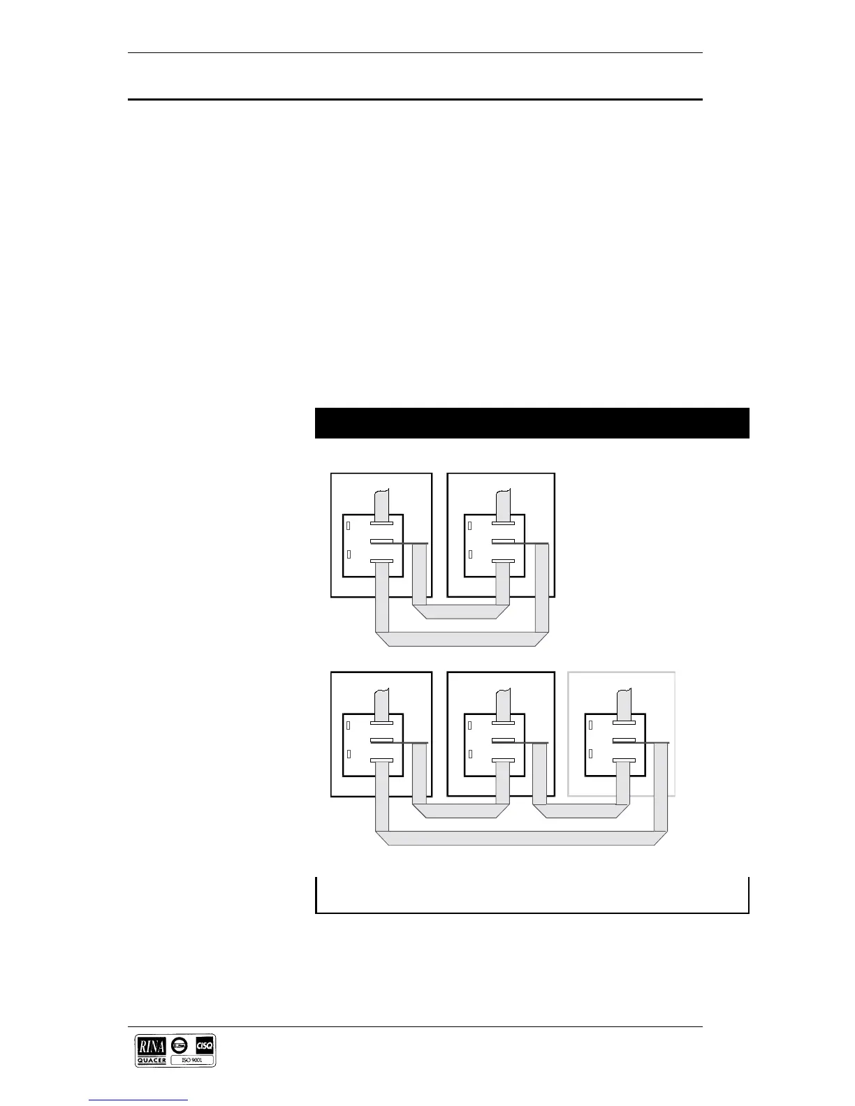
10. On the one-plus-one system only connect the parallel control ribbon
cables between the Parallel Interface Boards (Part no. 4590049 J) of
both modules. Connect one ribbon cable between sockets CN1 on
one board and CN2 on the other, and connect the second ribbon cable
between the remaining CN1 and CN2 sockets.
Caution
To maintain EMC compliance all external control and communications cables must be
screened.
CN3
CN2
CN1
CN3
CN2
CN1
CN3
CN2
CN1
CN3 CN3
CN2
CN2
CN1
CN1
Module 1 Module 2
Module 1 Module 2
Common Battery
Pa n e l
Figure 3-1 . Connecting the parallel interface cables
 Loading...