Chapter 4 - Optional equipment 7400 Series UPS User Manual
Option Board Kit (Part no. 77000005) Single Module and One plus One Systems
6310018a.02.doc
4-32
Issue 2
(02/98)
6. Connect auxiliary wiring required as shown in figure 4-18
Battery charging temperature compensation
temperature sensing element - TB1-1 and TB1-2
Reduced input current limit
normally open contacts - TB1-3 and TB1-4
Reduced battery current limit
normally open contacts - TB1-5 and TB1-6.
7. Calibrate the options using instructions sheet part number 77000008.
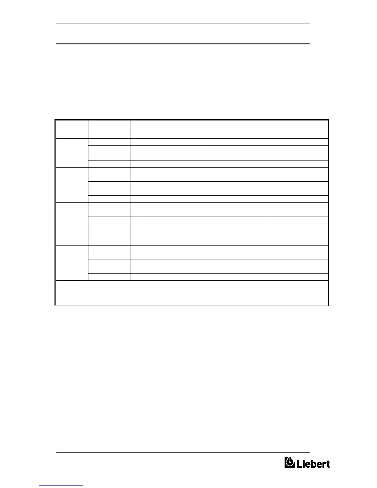
SHUNT LINK
POSITION
DESCRIPTION
1 1-2 Reduced Input current limit Calibration Mode.
2-3 Normal Operation.
2 1-2 Reduced Battery current limit Calibration Mode.
2-3 Normal Operation.
3 1-2 Reduced Input current limit: Link fitted - System enabled
Link not fitted - System Disabled.
3-4 Reduced battery current limit: Link fitted - System enabled
Link not fitted - System Disabled.
1-2 & 5-6 Reduced battery current activated when reduced input current limit isactive.
4 1-3 Temperature Compensation Calibration mode selected. (The remote temperature
sensor MUST be removed before operation in this mode.
2-4 Temperature Compensation mode selected.
5 1-2 LED 4 illuminates at temperatures set by SOT R26 (i.e. Battery Over Temp
Alarm).
2-3 LED 4 illuminates when the Temperature Compensation system becomes active.
6 1-2 Temperature compensation enabled: This applies to a 6 pulse Rectifier logic board
(part no. 4520049B) NOW OBSOLETE.
2-3 Temperature compensation enabled. 12 pulse Rectifier Logic board (part no.
4520073 Z).
No links Temperature compensation disabled.
Table 3 - Option board - Summary of link settings
 Loading...