MX-FR Series Modular Matrix Frames – User's Manual 135
Parameter Description Parameter Values
<src> Source type
R = analog RGB
Y
A = automatic analog
D
S = automatic input selection
<sig_type>
Signal type
sent to the crosspoint
A = auto (if the port is not HDMI-compatible the type will be DVI)
D = DVI (no audio)
=
if HDMI signal is present the type will be HDMI. If analog or
DVI signal is present the type will be DVI.
<audio> Audio signal presence
0 = no audio
D = embedded audio (from HDMI)
A = audio from the add-on board (if exists)
<hdcp> HDCP setting
0 = HDCP is disabled
1 = HDCP is enabled
<ps>
Port status, binary data
represented in HEX
format (read-only)
bit 3 bit 2 bit 1 bit 0
reserved
0 = not protected
1 = HDCP-protected
0 = 5V not detected
1 = 5V detected
<video>
The deteced signal type
(read-only)
= HDMI signal
D = DVI signal
R = RGBHV (analog signal with HV sync)
C = component (analog signal with embedded HV sync)
- = no video signal, no sync detected
#hdcp
Parameter Description Parameter Values
<timings_1>
Timing parameters
for more information about the measured values, please
contact Lightware Support
<timings_2>
<res>
The name of the
resolution (string)
short name in the case of SMPTE standard, otherwise
<width>x<height>p<refr_rate>, e.g. 1600x1200p60
Parameter Description Parameter Values
<color>
Color information;
binary data
respresented in HEX
format *
bit 4 bit 3 bit 2 bit 1 bit 0
4:4:4
4:2:2
(not
supported)
(not
supported)
<res>
The name of the
resolution (string)
<width>x<height>p<refr_rate>, e.g. 1600x1200p60
#audio
Parameter Description Parameter Values
<a_typ>
Audio type of the
embedded audio
(HDMI)
0 = no audio
P = 2-channel L-PCM
M = multichannel PCM
S = compressed audio
= HBR audio
D = DST audio
E = DSD audio
<a_samp>
Sampling frequency of
the embedded audio
(HDMI)
32 = 32 kHz
44 = 44.1 kHz
48 = 48 kHz
88 = 88.2 kHz
96 = 96 kHz
176 = 176.4 kHz
192 = 192 kHz
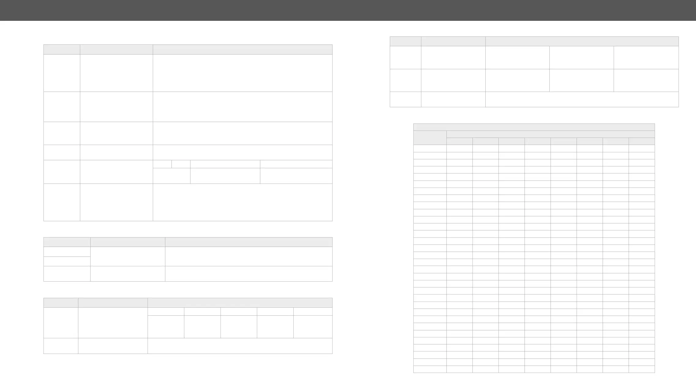
<a_ch>
Speaker locations
(only at M-PCM audio)
This byte describes the different speaker locations allocated to the
audio channels. See the following table for the possible values.
Test Pattern Settings
Speaker Locations
<ff> value
Channel Number
8 7 6 5 4 3 2 1
00 FR FL
01 LFE FR FL
02 FC FR FL
03 FC LFE FR FL
04 RC FR FL
05 RC LFE FR FL
06 RC FC FR FL
07 RC FC LFE FR FL
08 RR RL FR FL
09 RR RL LFE FR FL
0A RR RL FC FR FL
0B RR RL FC LFE FR FL
0C RC RR RL FR FL
0D RC RR RL LFE FR FL
0E RC RR RL FC FR FL
0F RC RR RL FC LFE FR FL
10 RRC RLC RR RL FR FL
11 RRC RLC RR RL LFE FR FL
12 RRC RLC RR RL FC FR FL
13 RRC RLC RR RL FC LFE FR FL
14 FRC FLC FR FL
15 FRC FLC LFE FR FL
16 FRC FLC FC FR FL
17 FRC FLC FC LFE FR FL
18 FRC FLC RC FR FL
19 FRC FLC RC LFE FR FL
1A FRC FLC RC FC FR FL
1B FRC FLC RC FC LFE FR FL
1C FRC FLC RR RL FR FL
1D FRC FLC RR RL LFE FR FL
1E FRC FLC RR RL FC FR FL
1F FRC FLC RR RL FC LFE FR FL