3. Product Overview MX-FR Series Modular Matrix Frames – User's Manual 29
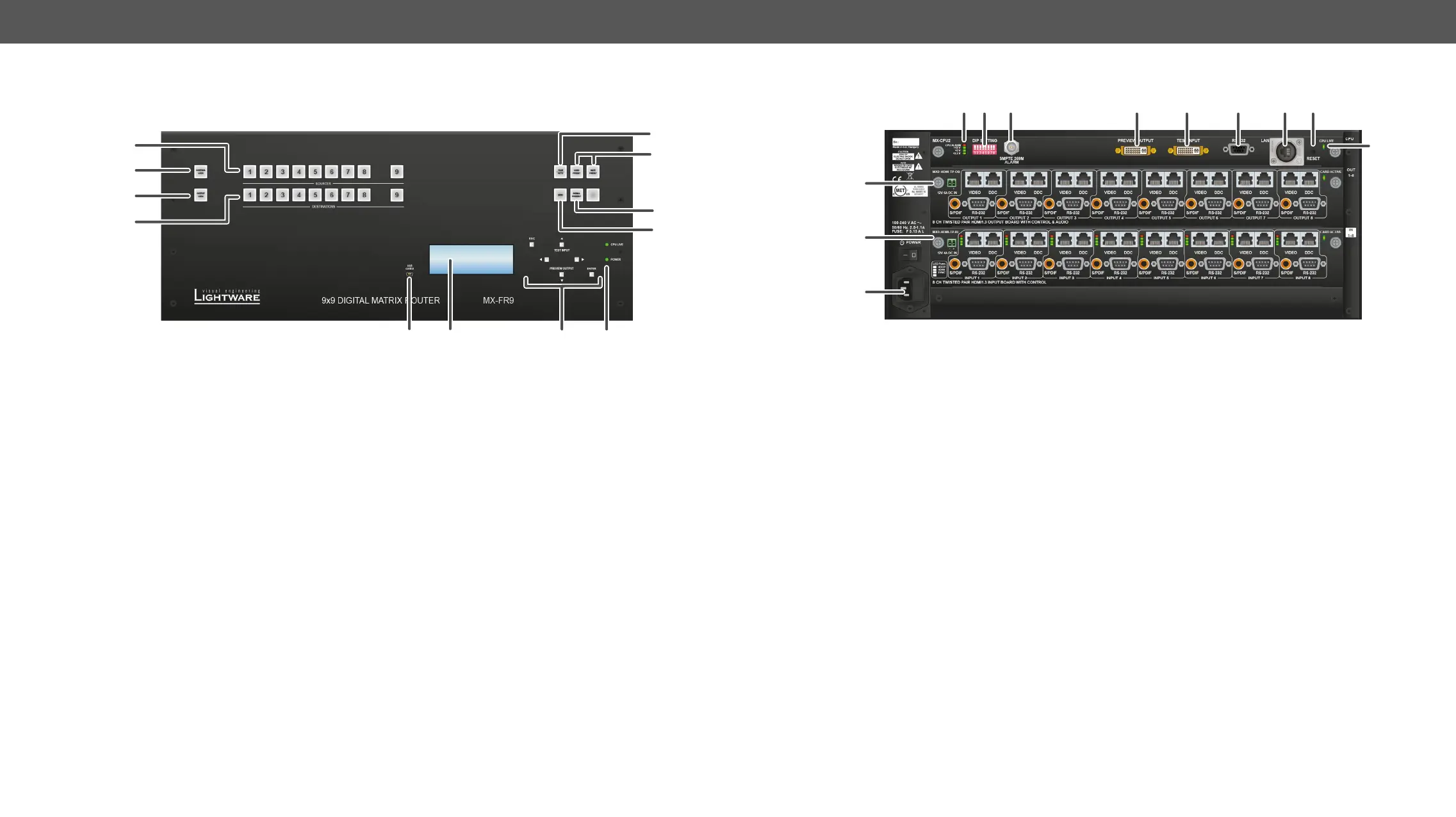
MX-FR9
Front View
12 3
4 5 6 7 8
9
q
1
USB control USB connection for Lightware
Device Controller software.
2
Menu
display
Displays status information
and menu operation.
3
Menu
navigation
Arrows, escape, and enter
buttons for menu navigation.
4
Status LEDs CPU live LED blinks to indicate
normal operation. Power LED
shines green when the router
is powered on.
5
Control lock Press long to disable or enable
shines red, all operations on
front panel are prohibited.
6
Output lock Locks one (or more) outputs.
Inhibits accidental input
changing on protected output.
7
Source
buttons
Select an input or preset or to
1
Status LEDs LED indicators for internal DC
power voltages and alarm.
2
DIP settings Special settings can be made
with these switches.
3
Alarm out Standard SMPTE 269M alarm
output with BNC connector.
See the Alarm Output section
for more information.
4
Preview
output
DVI output connector that is
directly connected to the 9th
output. See the DVI Inputs and
Outputs and the Test Input
and Preview Output sections
for more information.
5
Test input DVI input connector, which can
for the 9th input. See the DVI
Inputs and Outputs and the
Test Input and Preview Output
sections.
6
Serial port 9 pole D-SUB female connector
for RS-232 serial connection.
See the RS-232 Ports section
for more information.
8
Destination
buttons
Destination buttons can be
used to select an output, or
state.
9
Take / Auto Displays the current switching
mode (TAKE or AUTOTAKE).
Long press toggles the
switching mode, short press
executes switching in TAKE
mode.
q
Preset
buttons
Load preset: apply a previously
saved crosspoint preset from
one of the preset memories.
Save preset: stores the current
crosspoint state in one of the
preset memories.
w
EDID mode Switches the Menu display
to EDID menu allowing EDID
switch, EDID save etc.
e
Signal
present
Displays live sources and
attached sinks on source and
destination buttons.
7
Ethernet
port
Remote control port for
connecting the unit to Local
Area Network (LAN) and
performed over this interface.
See the Ethernet Ports section
for more information.
8
Reset
button
Reset button; reboots the
matrix. It has the same result
as disconnecting the device
from the power source and
reconnecting it again.
9
CPU live CPU live LED blinks to indicate
normal operation.
q
Output
boards
Modular output board slots.
Connect sink devices to these
connectors.
w
Input boards Modular input board slots.
Connect source devices to
these connectors.
e
Power Mains switch and AC power
connector.