3. Product Overview MX-FR Series Modular Matrix Frames – User's Manual 32
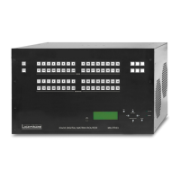
Symmetrical Analog Stereo Audio
together.
Unbalanced audio signals can be connected as well. For asymmetrical output, connect only + and ground.
For asymmetrical input, connect + and ground to the source and connect – to the ground.
Compatible Plug Type
Please see the short guide about the audio cable wiring in the section.
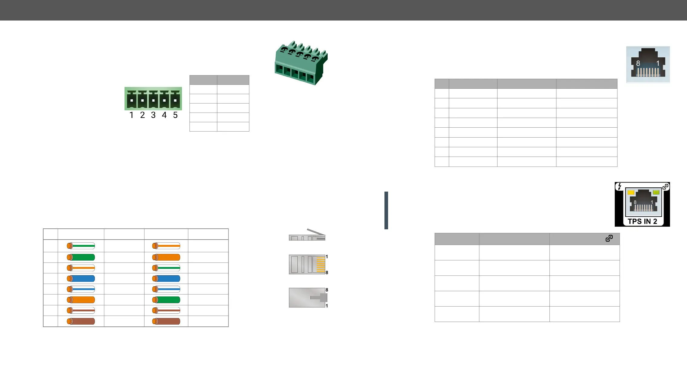
RJ45 Connectors and Twisted Pair Cables
The Wiring of Twisted Pair Cables
standards.
Pin nr. Signal
1 Left +
2 Left -
3 Ground
4 Right -
5 Right +
Top
Bottom
Side
Pin TIA/EIA T568A Wire color TIA/EIA T568B Wire color
white/greenwhite/orange3
white/green white/orange1
blue blue4
white/blue white/blue5
brown8 brown
white/brown7 white/brown
greenorange6
green orange2
MX-TP Input and Output Ports
DVI-TP-IB and MX-DVI-TP-OB, but available on the MX-DVI-TP-IB+ and MX-DVI-TP-OB+
boards.
Pin VIDEO IN/OUT DDC IN DDC OUT
1 TMDS Data0+ CEC (no conn.) CEC (no conn.)
2 TMDS Data0- Hot Plug Detect (in) Hot Plug Detect (out)
3 TMDS Clock+ RS-232 RX RS-232 RX
4 TMDS Data1+ DDC CLK DDC CLK
5 TMDS Data1- +12V (out) +12V (out)
6 TMDS Clock- RS-232 TX RS-232 TX
7 TMDS Data2+ DDC SDA DDC SDA
8 TMDS Data2- GND GND
MX-TPS, MX-TPS2 Inputs and Outputs
ATTENTION!
LAN cables to the TPS connectors. If the port of the TPS board was set to AUTO
mode, it is able to recognize the LAN cable and swap to Ethernet fallback mode
automatically. In this case, the port works as an Ethernet switch, but a TPS CAT
cable is not allowed to be connected to the Ethernet port.
LED1, Amber
LED2, Green
OFF
Remote power is
disabled
No TPS link
Blinking
Low power mode,
RS-232 and Ethernet
Blinking
Low power mode,
only RS-232
Blinking
Ethernet fallback mode
ON
Remote power is
enabled
TPS link is active