3. Product Overview MX-FR Series Modular Matrix Frames – User's Manual 24
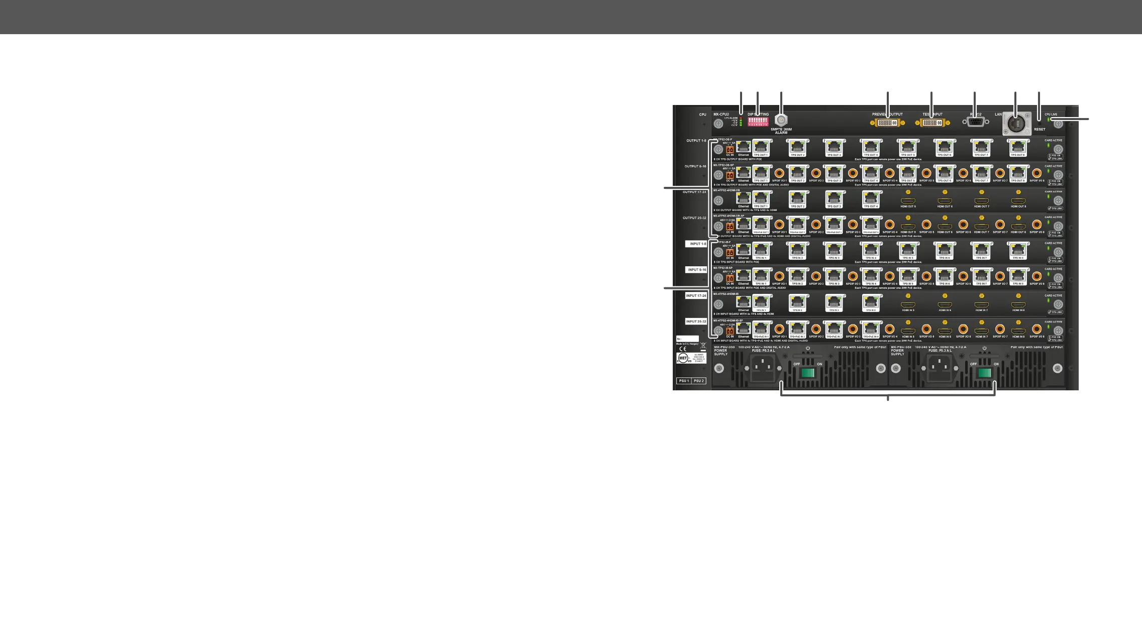
Rear View
1
Status LEDs LED indicators for internal DC power voltages and alarm.
2
DIP settings Special settings can be made with these switches.
3
Alarm out Standard SMPTE 269M alarm output with BNC connector. See the Alarm
Output section for more information.
4
Preview output DVI output connector that is directly connected to the 33rd output. See the
DVI Inputs and Outputs and the Test Input and Preview Output sections for
more information.
5
Test input
input. See the DVI Inputs and Outputs and the Test Input and Preview Output
sections.
6
Serial port 9 pole D-SUB female connector for RS-232 serial connection. See the RS-232
Ports section for more information.
7
Ethernet port
interface. See the Ethernet Ports section for more information.
8
Reset button Reset button; reboots the matrix. It has the same result as disconnecting the
device from the power source and reconnecting it again.
9
CPU live CPU live LED blinks to indicate normal operation.
q
Output boards Modular output board slots. Connect sink devices to these connectors.
w
Input boards Modular input board slots. Connect source devices to these connectors.
e
Power supplies Hot swap slots for power supply units. See the Powering on section for more
information.
1 2 3
4 5 6 7 8