Instruction Manual for TECH-system type 239
______________________________________________________________________________
Page 12 of 39 june 2020 ver. 09
LINAK Danmark A/S - Mønstedsvej 9 8600 Silkeborg - Telefon 86803611 - www.linak.dk
Connection and installation
Screw terminals are used to connect the TR-EM-239 motor control unit. A general description of the
individual terminals is presented below. See the diagrams later in this manual for information about the
correct connection of the different actuators.
Fitting the motor control unit
Four versions of the motor control unit TR-EM-239 are available:
5. Separate PCB: Order no. TR-EM-239
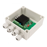
6. PCB fitted in box: Order no. TR-EM-239-H
7. PCB mounted on DIN rail for panel mounting Order no. TR-EM-239-R
8. PCB fitted in box with power supply: Order no. TR-EM-239-T-230
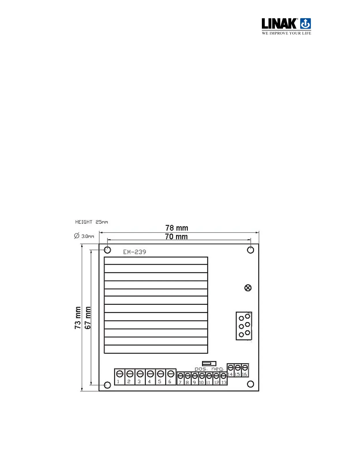
Separate PCB – TR-EM-239
The PCB is fitted using four 3 mm diameter screws and connected to an external power supply.
The height of the PCB is 25 mm.
 Loading...