Instruction Manual for TECH-system type 239
______________________________________________________________________________
Page 16 of 39 june 2020 ver. 09
LINAK Danmark A/S - Mønstedsvej 9 8600 Silkeborg - Telefon 86803611 - www.linak.dk
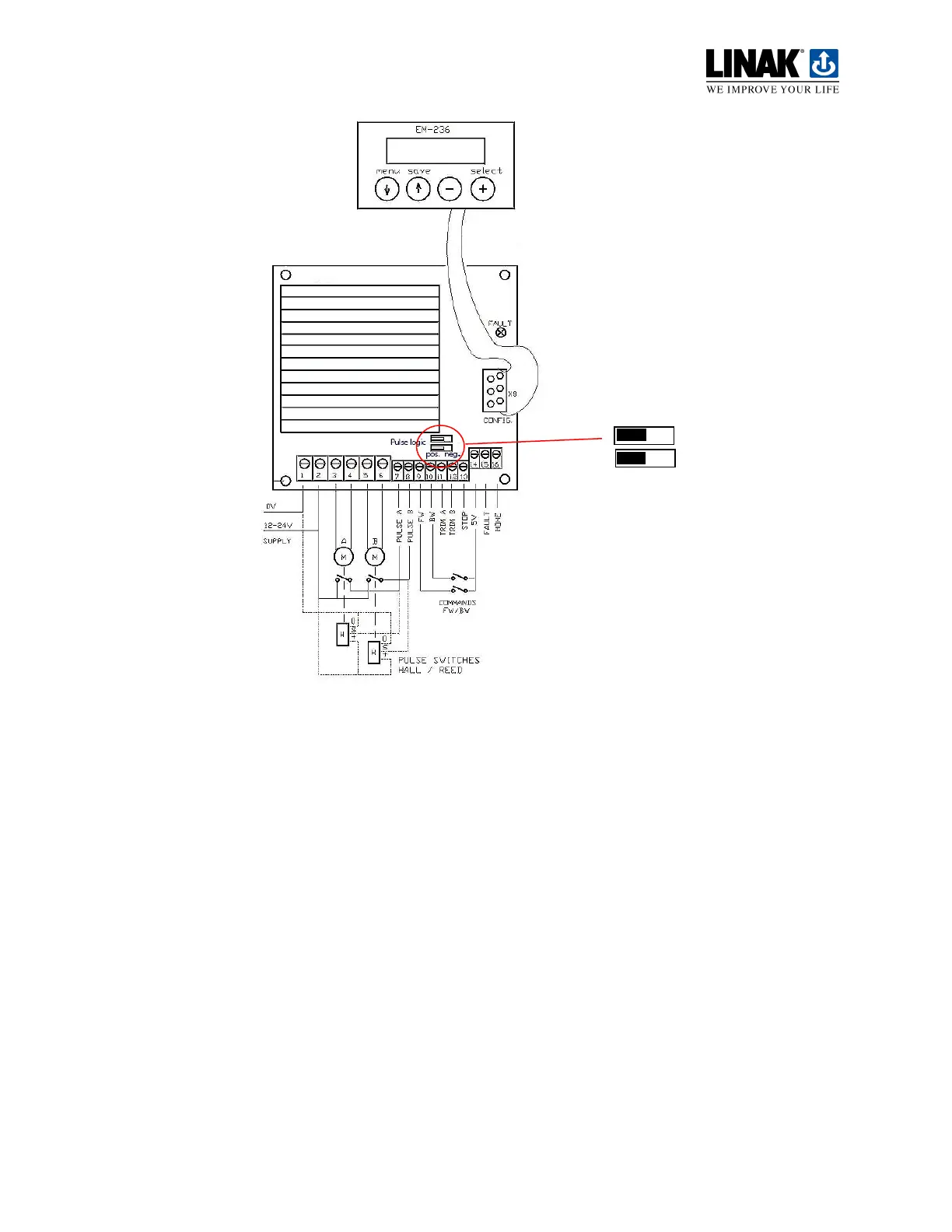
Connection of the motor control unit
Terminal 1: Supply voltage (- gnd)
Terminal 2: Supply voltage (+ 12–24 V DC) smoothed voltage
Terminal 3: Voltage to motor on actuator 1
Terminal 4: Voltage to motor on actuator 1
Terminal 5: Voltage to motor on actuator 2
Terminal 6: Voltage to motor on actuator 2
Terminal 7: Reed/hall signal from actuator 1
Terminal 8: Reed/hall signal from actuator 2
Terminal 9: If terminals 9 + 14 are connected, the actuators run FORWARDS
Terminal 10: If terminals 10 + 14 are connected, the actuators run BACKWARDS
Terminal 11: Hall -A signal from actuator 2 /OR Service operation for actuator 1. If terminals
11 + 14 are connected, ONLY actuator 1 will respond when operation is activated.
Terminal 12: Hall -B signal from actuator 2 /OR Service operation for actuator 2. If terminals
12 + 14 are connected, ONLY actuator 2 will respond when operation is activated.
Terminal 13: STOP. If terminals 13 + 14 are connected, all operation will stop (end stop
switch)
Terminal 14: 5 V output.
Terminal 15: Error output. External relay, if any, connected – (gnd)
Terminal 16: HOME. Actuators forced to return to starting position and system initialised.
Pulse feedback
 Loading...