24
PULSE OUTPUT DEVICE (POD)
Pulse Output
Device (POD)
Port
LectroCount LCR-II
Gallons
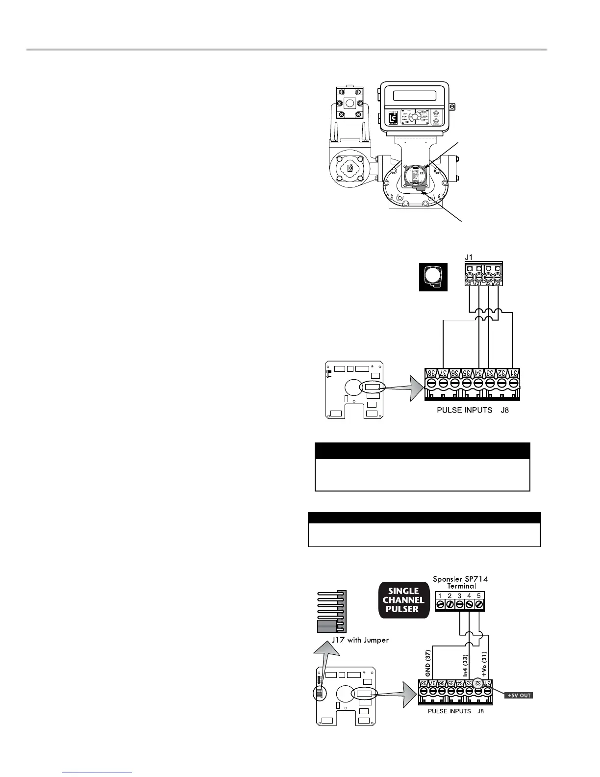
GND (37)
CHB (34)
CHA (33)
+Vo (31)
POD Pulser
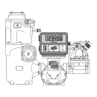
Meter System with Pulse Output Device
Pulse Output Device (POD)
Installation
installed onto the meter and wired to the LCR-II at the
factory. The POD can also be ordered separately and
mechanical installation instructions, refer to the POD
manual. Instructions for wiring the POD to the LCR-II are
provided on this page.
Materials needed for wiring valves:
Not supplied
with the POD
conduit connectors or cable glands
To wire a POD to the LCR-II:
1. Attach cable glands and/or conduit connectors to the
POD and the LCR-II port(s).
2. Thread the wires through a piece of weatherproof conduit
cut-to-length from the POD port to a LCR-II port.
3. Run the weatherproof conduit between the POD and
the LCR-II housing, pull the wires through the ports, and
tighten the connectors.
4. Connect the four POD terminals to four terminals on the
Single Channel Pulse Inputs
The LCR-II is compatible with the many single channel
pulse, you will need version v1.15 (or above) of the
To a single channel pulse output to the LCR-II
SR260 base software.
board. Schematic on the right shows wiring to a Sponsler SP714.
Disconnect the power before working on the CPU board.
Disconnect Power
This wiring schematic applies to pulse output devices 1
through 4 only.
Pulse Output Devices 1, 2, 3, & 4 Only

 Loading...