26
REMOTE DISPLAY AND AUXILIARY OUTPUTS
Auxiliary Outputs
The LCR-II provides three open drain transistor auxiliary
outputs for different external devices such as pump
can be connected to the LCR-II.
Auxiliary Output 1 (Out 1)
This signal has four output settings: Off, On, On During
Auxiliary Output 2 (Out 2)
This signal has three output settings: Off, On, On During
Pulse Output (Out 3)
This output represents the gross delivery quantity for
uncompensated deliveries or the net delivery quantity
(for compensated deliveries). This output is a real time
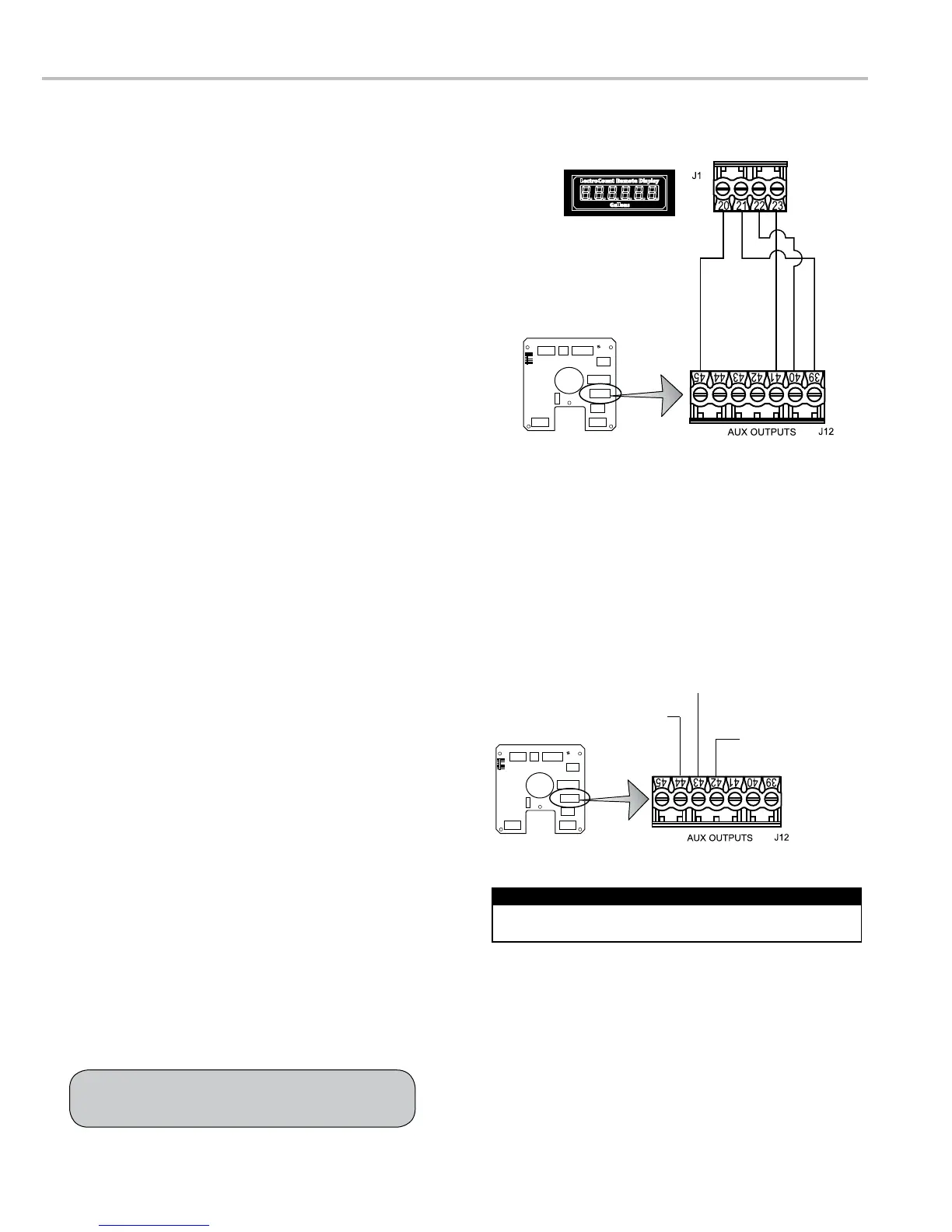
Auxiliary Outputs 4 & 5
(LectroCount Remote Display)
LectroCount Remote Display, but they can also be used
with other types of displays. Signals from these outputs
duplicate the volume data sent to the LCR-II display.
Refer to the LectroCount remote display manual for
complete installation instructions.
To wire an external display to the LCR-II:
1. Attach cable glands and/or conduit connectors to the
display and the LCR-II port(s).
2. Thread the wires through a piece of weatherproof conduit
cut-to-length from the display port to a LCR-II port.
3. Run the weatherproof conduit between the display and
the LCR-II housing, pull the wires through the ports, and
tighten the connectors.
4. Connect the four display terminals to four terminals on
To select the Auxiliary Output settings, refer to the
LectroCount LCR-II Setup and Operation manual.
Remote Display
GND/Black (41)
DN/Green (40)
+Vo/Red (45)
UP/White (39)
Auxiliary Output 1 (Out 1)
Auxiliary Output 2 (Out 2)
Pulse Output (Out 3)
Disconnect the power before working on the CPU board.
Disconnect Power

 Loading...