25
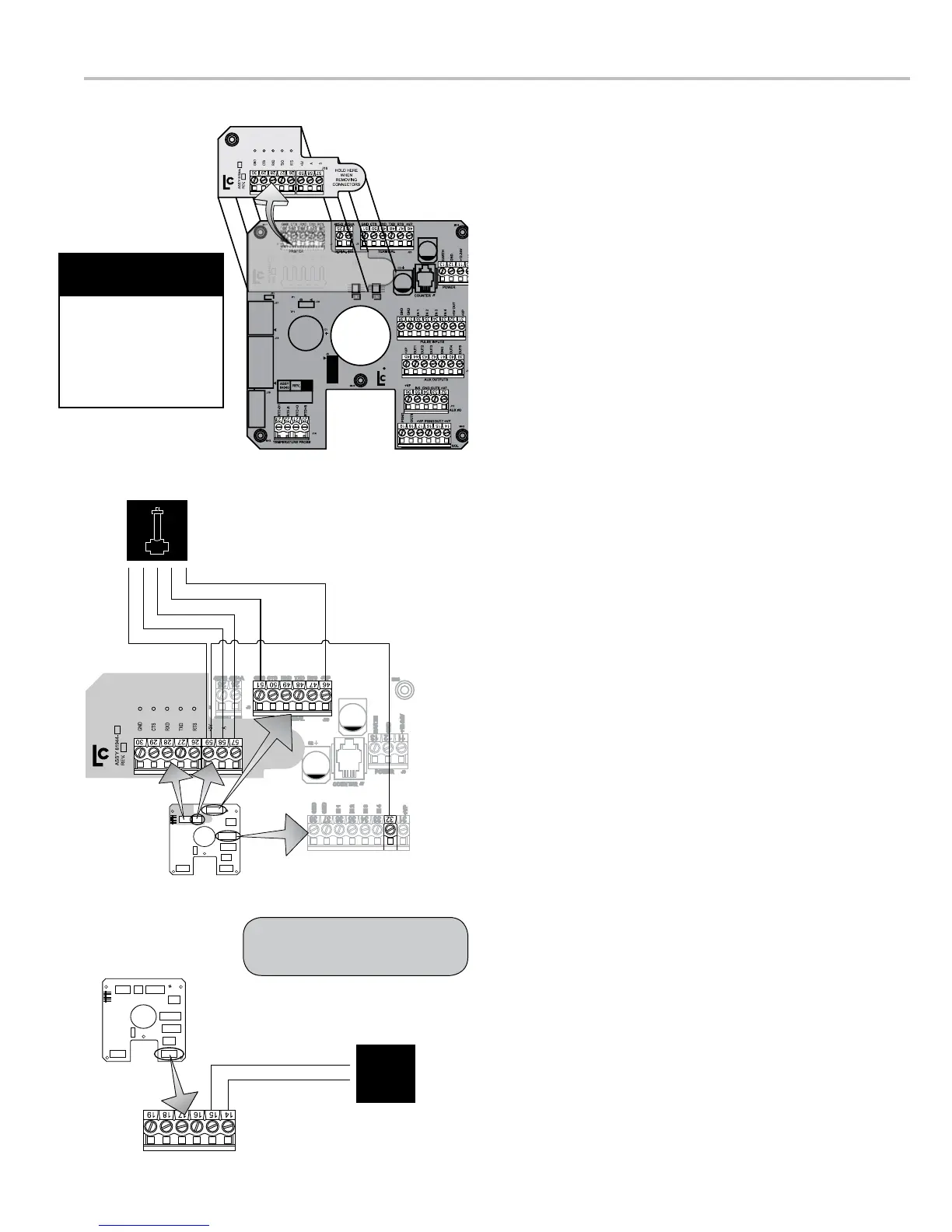
Transducer Installation
separately and installed onto a meter system already in
transducer to the LCR-II are provided on this page.
81944) that mounts directly to the LCR-II CPU board.
shutdown device, such as a valve or a dead-man. The
shutdown control must be wired to the LCR-II and should
draw no more than 1 A.
CPU board. Leave the wires in the terminals.
2. Remove the screw at the top left corner of the LCR-II
CPU board.
3. Plug the 81944 board into the J1 connectors on the LCR-
II CPU board.
the screw provided.
6. Plug terminal J16 into the 81944 board.
LC recommends running the cable through weatherproof
conduit.
the LCR-II CPU board and J16 on the 81944 board.
10. Route a two wire cable from the shutdown control device
Secure the cable gland. LC recommends running the
cable through weatherproof conduit.
11. Connect the two wires from the shutdown control device
11 12 13
PRINTER SERIAL 485 TERMINAL
POWER
COUNTER
MH1
CTS RXD TXD RTS GNDGND 485+A485-B CTS RXD TXD RTS +VP
EARTH
GND
GND
IN 1
IN 2
IN 3
IN 4
+5V OUT
+VP
GND
+12-24V
MH4
J20
J6
J3J2J1
J7
J7
C2
24
25
∆P Transducer
+5V(Out)/Jumper (59 to 32)
A/Blue (58)
+5V/Red (59)
B/Yellow (57)
GND/White (51)
+VP/Black (46)
B
Dead-Man
Shutdown
Auxiliary
Device
+Vo
Out7
The shutdown device should
draw no more than 1A.
When removing the J1
or J16 terminal from
the 81944 board, hold
down the right end of
the main CPU board to
prevent exing.
Be Careful with the
CPU Board

 Loading...