3-8 CHAPTER 3: SETTING INTO OPERATION
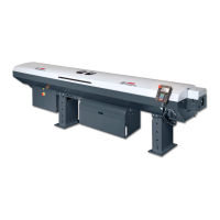
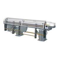
ALPHA 552
4. ELECTRICAL CONNECTIONS
Before connecting, check to make sure that the voltage of the barfeed system
corresponds to the one provided by the lathe. The voltage of the barfeed system is
indicated on the identification plate.
Voltage: 3 x 220-480 V, 50 / 60 Hz + Ground (± 10%)
Maximum voltage: 3 x 220 V = 6 A
3 x 480 V = 3 A
In the case where the voltage supplied by the lathe does not match that provided for the bar feeder, the
following must be adapted:
a) Transformer T1
b) Hydraulic pump motor
The LNS barfeed systems are equipped with their own thermal protection systems (breakers, thermal
relays and fuses, etc.). The power supply for the barfeed system should be connected to the output of a
breaker mounted in the electrical control box of the lathe (10 A max.).
For the wiring inside the lathe, the section of the cables should be at least 1.5 mm
2
(AWG 16).
Electrical interface lathe – barfeed
Always refer to the electrical diagrams shipped with the barfeed system and placed in the electrical
cabinet. Although an example of an interface diagram is provided, the diagram for the interface
corresponding to your device, essential when making the electrical connection, is located inside the
electrical cabinet.
Only LNS (or certified technician)bar is authorized to modify the interface or parameter
system.