Do you have a question about the LNS TRYTON 112 and is the answer not in the manual?
Describes the manual's structure, including chapters, points, paragraphs, and lists.
Explains the meaning of various symbols and terms used throughout the manual.
Provides essential safety guidelines for operating the equipment safely.
Describes the safety features designed to prevent accidents and ensure user protection.
Lists technical specifications like weight, dimensions, power supply, and hydraulic oil type.
Provides dimensions and layout information for optimal placement of the bar feed system.
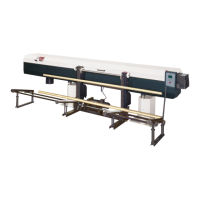
Identifies and describes the various components and parts of the bar feed system.
Details instructions for safely transporting the bar feed system.
Covers the process of mounting the bar feed system onto the lathe.
Instructions for securely anchoring the bar feed system to the floor for stability.
Explains how to connect the bar feed system to the lathe and compressed air.
General overview of the electrical components and their conformity to standards.
Details the layout and components within the electrical control cabinet.
Presents electrical symbols and their corresponding component designations.
Explains the interface cables and their connection to the lathe.
Specifies voltage, power requirements, and connection precautions for the power supply.
Details the 24V DC power supply and emergency stop signals from the lathe.
Explains various signals sent from the bar feeder to the lathe for control.
Summarizes key safety interlocks and procedures for the interface connection.
Introduces pneumatic elements and the required air pressure for operation.
Details the function and layout of the air filtering and pressure regulation unit.
Describes the pneumatic valve assembly for control and monitoring of the system.
Explains how electro-valves control pneumatic cylinders and manual activation.
General description of the hydraulic system and its principle of operation.
Identifies and lists the hydraulic components on the bar feed system.
Details the hydraulic block, including pressure gauge, regulator, and switch.
Instructions for filling and draining the hydraulic tank with oil.
Presents hydraulic symbols and the overall hydraulic diagram.
Describes the barrel's function in storing and feeding bars.
Explains the connector's role in lodging the pusher and feeding hydraulic fluid.
Describes the pusher's function in grasping and pushing material.
Explains the movable vise's role in inserting and extracting material.
Describes the optional loading arm for facilitating maintenance.
Introduces the remote control and its interface segments.
Guides the operator through the initial power-up procedure.
Provides a flowchart for operating the system in manual mode.
Explains how to start and run the bar feeder in automatic mode.
Introduces parameter and function settings for configuring the bar feed system.
Lists factors like installation, clearance, and material that affect performance.
Details how bar material properties affect feeding and performance.
Compares different collet systems for their effectiveness in clamping.
Provides procedures for maintaining the hydraulic, pneumatic, and mechanical systems.
Provides a form for ordering parts and accessories.
Lists contact information for LNS agencies worldwide.
Offers an example of programming for the lathe and bar feeder.
Provides a table for converting metric measurements to inches.
Offers a table for converting measurements of shaped bars.
| Brand | LNS |
|---|---|
| Model | TRYTON 112 |
| Category | Industrial Equipment |
| Language | English |