8 - 10 CHAPTER 8 : OPERATION
TRYTON 112 CNC
Note :
Under certain
conditions, it
is possible to
perform
manual
movements
during the
automatic
cycle. .
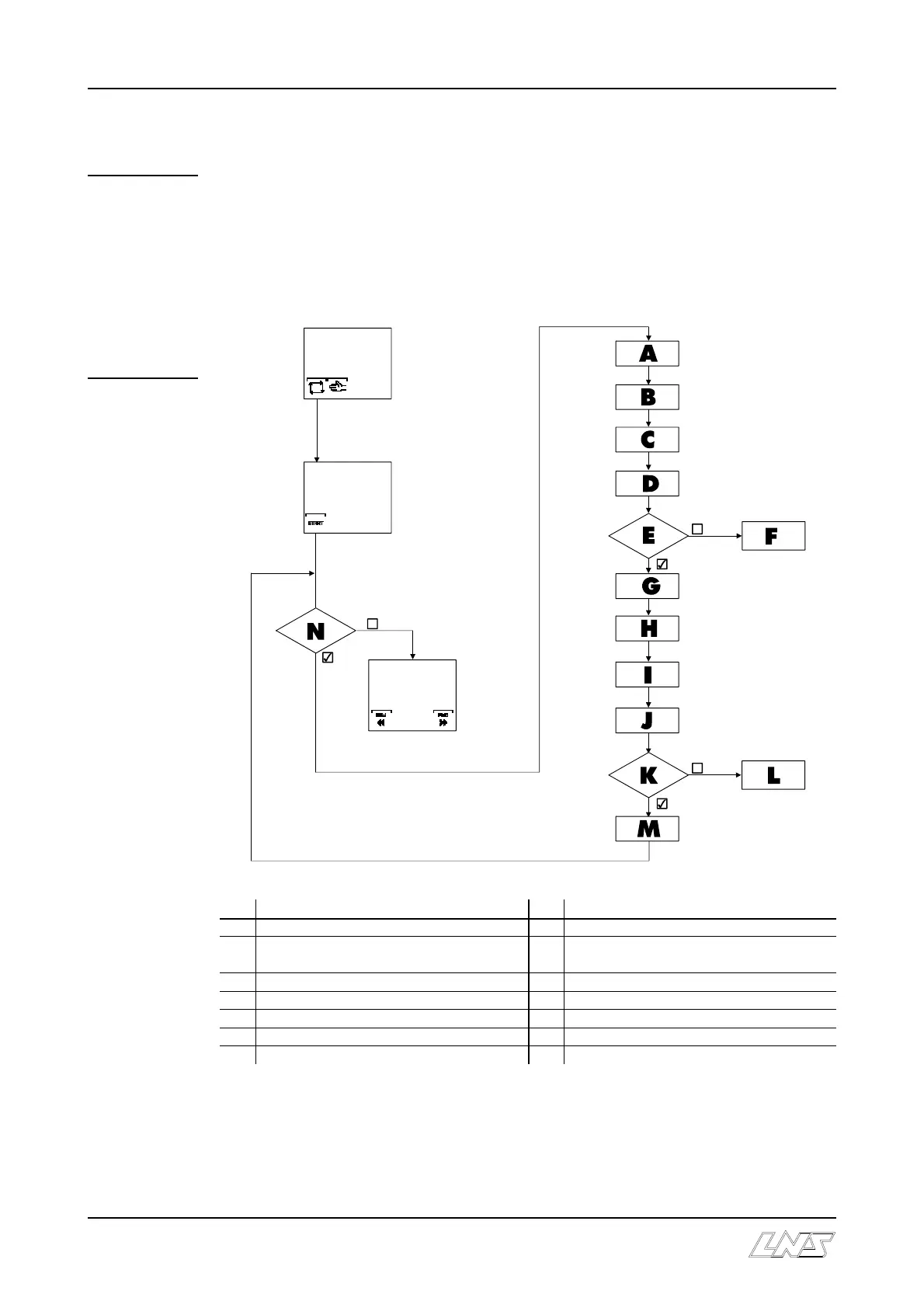
4.2 Flow chart
The sequence of event of the flow chart may vary depending on the interface and
operation parameters. The diagram below shows a standard cycle.
To turn on the automatic cycle, a bar must be introduced in the clamping system of the
lathe. Then, proceed as follows :
Sequence Sequence
A Production cycle, machining parts H Barrel indexing
B End of bar signal I The movable vise grasps and advances the
bar
C Feeding pusher reverses to reference point J Introduction of the bar into the collet
D The movable vise extracts the remnant K Monitoring of material presence
E Monitoring of material presence L Fill the bar magazine
F Remnant not extracted M Feeding pusher positions bar to Top-Cut
G The movable vise moves back N Closing the lathe chuck jaw