CHAPTER 4: ELECTRICS 4 - 1
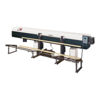
TRYTON 112 CNC
CHAPTER 4 : ELECTRICS
1. ELECTRICAL EQUIPMENT 4-2
1.1 Description 4-2
1.2 Layout of the elements 4-3
1.3 Description of the electrical elements of the bar feed system 4-4
1.3.1 Pump motor 4-4
1.3.2 Stationary control 4-5
2. ELECTRICAL CONTROL CABINET 4-6
2.1 Layout of the elements in the electrical control 4-6
2.2 Description of the elements in the electrical control 4-7
2.2.1 Main disconnect switch 4-7
2.2.2 Circuit breakers 4-8
2.2.3 Transformer 4-9
2.2.4 Programmable control (inputs/outputs) 4-10
3. DIAGRAMS 4-13
3.1 Symbols 4-13
3.2 Electrical diagram 4-14
4. INTERFACE 4-19
4.1 Description 4-19
4.2 Diagrams 4-20
4.3 Connections 4-21
4.3.1 Main power supply 4-21
4.3.2 Signals from the lathe to the bar feed system 4-22
4.3.3 Signals from the bar feed system to the lathe 4-24
4.3.4 Options 4-25
4.3.5 Recapitulation of safety instructions related to the interface 4-25