6 - 2 CHAPTER 6 : HYDRAULICS
TRYTON 112 CNC
1. HYDRAULIC EQUIPMENT
Please read the safety precautions described at the beginning of this manual
before handling the following devices.
1.1 Description
The guidance principle of the Tryton 112 bar-feeder consist in creating an oil film around
the rotating bar that will help maintain it in the centre of the guidance tube thus avoiding
all vibration and friction.
The hydraulic oil is contained in a tank. It is drawn up by a motor pump and injected in
the connector. This pressure causes the pusher to advance and also guides the bar.
A pressure switch measures the pressure at the outlet of the pump.
A level allows the monitoring of the filling rate of the hydraulic tank.
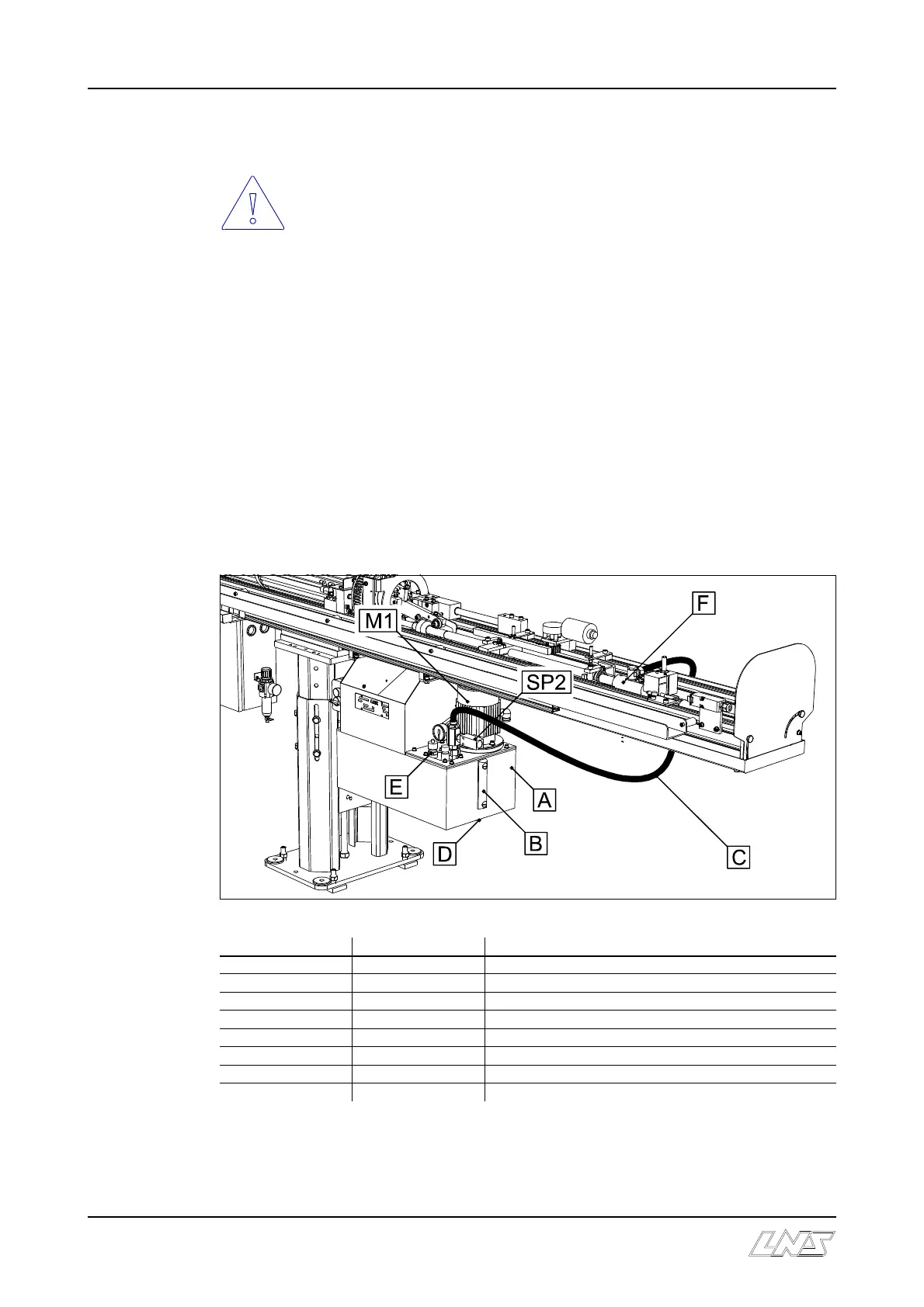
1.2 Layout of the elements
Designation Article No Description
A - Hydraulic tank / capacity 25 liters
B 2.055 Level
C 112.012.043 Connection block feed tube
D 3.127 Drain plug
E (1) Hydraulic block
F - Connector block
M1 3.189 Hydraulic pump motor
SP2 4.050 Pressure control switch
(1) See below