4 - 14 CHAPTER 4: ELECTRICS
TRYTON 112 CNC
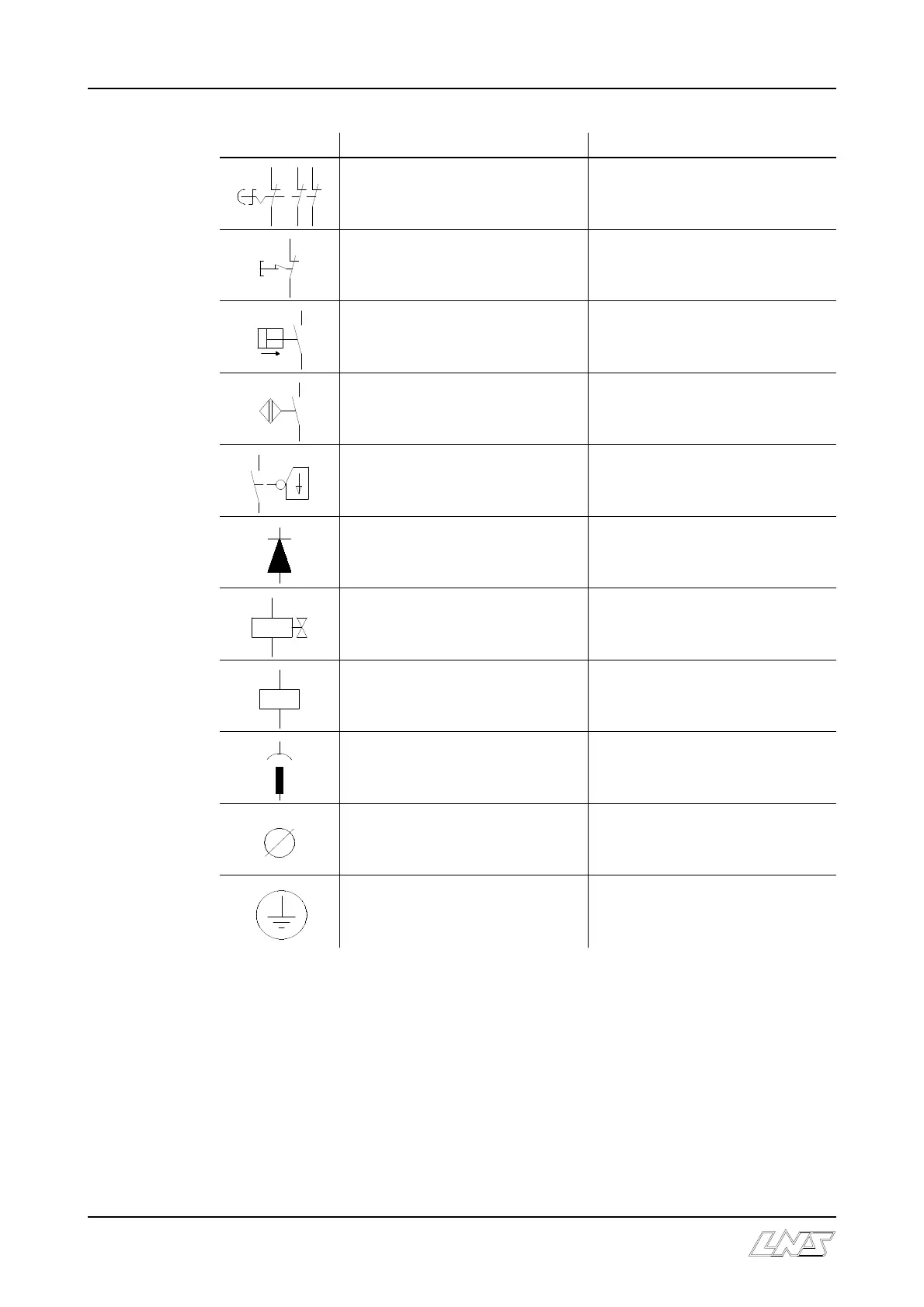
Symbole Description Désignation
Emergency stop push button bar
feeder side
STP
Emergency stop lathe side
Pressure switch SP1 : Pneumatic
SP2 : Hydraulic
Switch SQ1-7 : Proximity switch
SQ8 : Reed proximity switch
Safety switch SQ10 / SQ11
Diode
Solenoid YV10 / YV11 / YV12 / YV13
Relay KA2 / KA3A / KA3R / KA4 /
R1 / R2 / R3 / R4 / R5
Terminal pin on interface plugs
Terminal block
Grounding contact
3.2 Electrical diagram
The electrical diagram consists of four parts and is contained in the electrical control
cabinet. Should it differ from the one shown on the following pages, the one contained in
the electrical cabinet should be referred to.