CHAPTER 5 : PNEUMATICS 5 - 7
TRYTON 112 CNC
3.3 Description of the elements
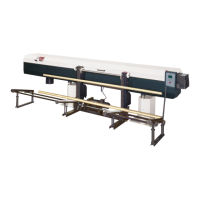
3.3.1 Electro-valves
Directly controlled by the PLC, the electro-valves activate the pneumatic cylinders
By pressing the key (C), the pneumatic cylinders can be activated manually. This maneuver
may prove to be useful during tests or maintenance.
Designation Description
A Sortie d’air
B Electrical connection
C Key
D Control LED
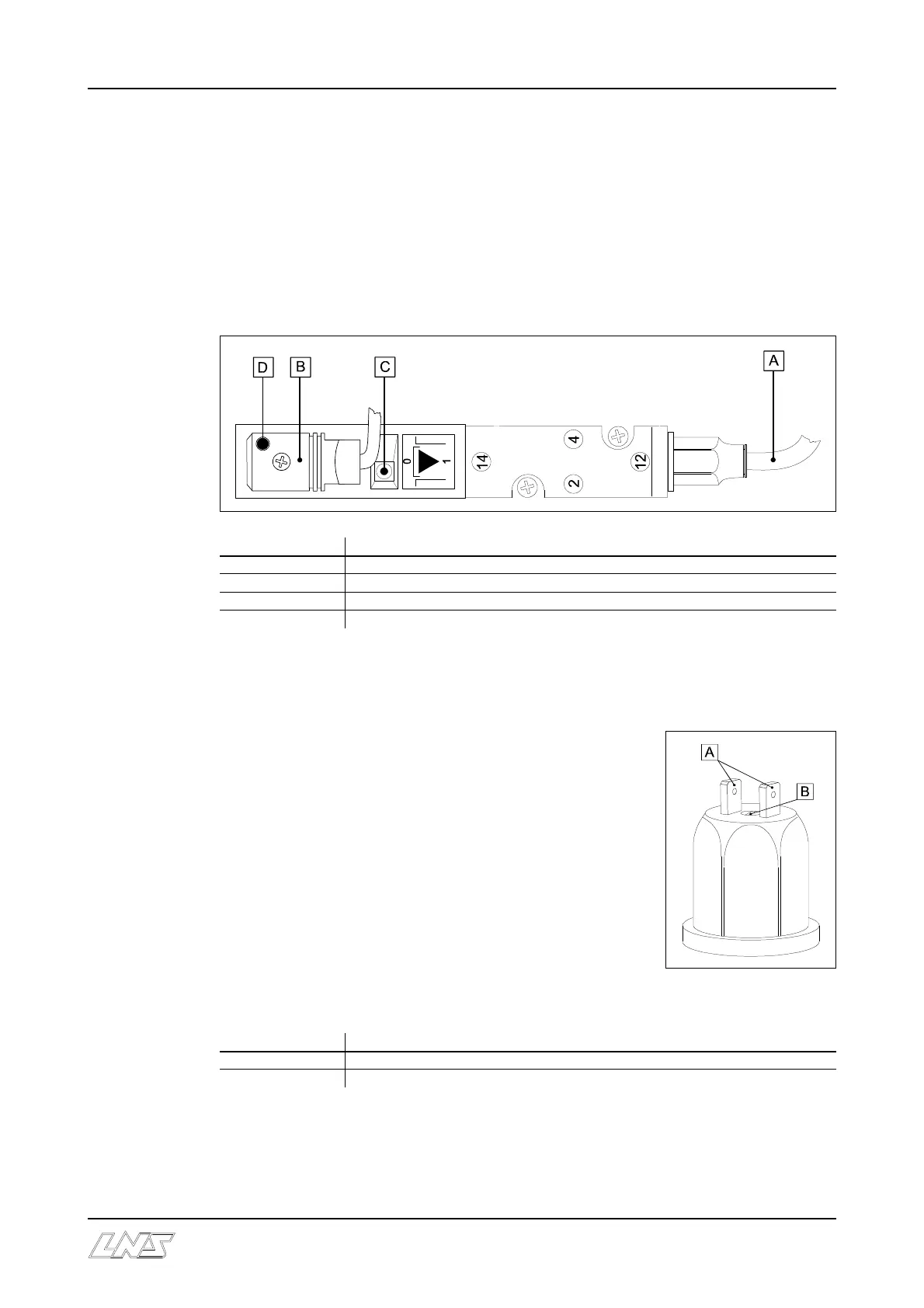
3.3.2 Pressure switch
For the Tryton 112 bar feed system, the service pressure must
be at least 5 bar (75 Psi).
The pressure switch serves to confirm that this pressure is
present and adequate.
Setting :
• By tightening screw (B), the point of release decreases; by
loosening it, it increases.
• On the air valve assembly, decrease pressure and check on
the manometer at the point of release. Adjust to 2 bar (30
Psi).
Designation Description
A Terminal for electrical connections
B Adjusting screw