CHAPTER 4: ELECTRICS 4 - 13
TRYTON 112 CNC
3. DIAGRAMS
3.1 Symbols
The electrical diagrams of the Tryton 112 bar feed system were made in accordance with the
ISO/IEC 204-1, 617 international electricity
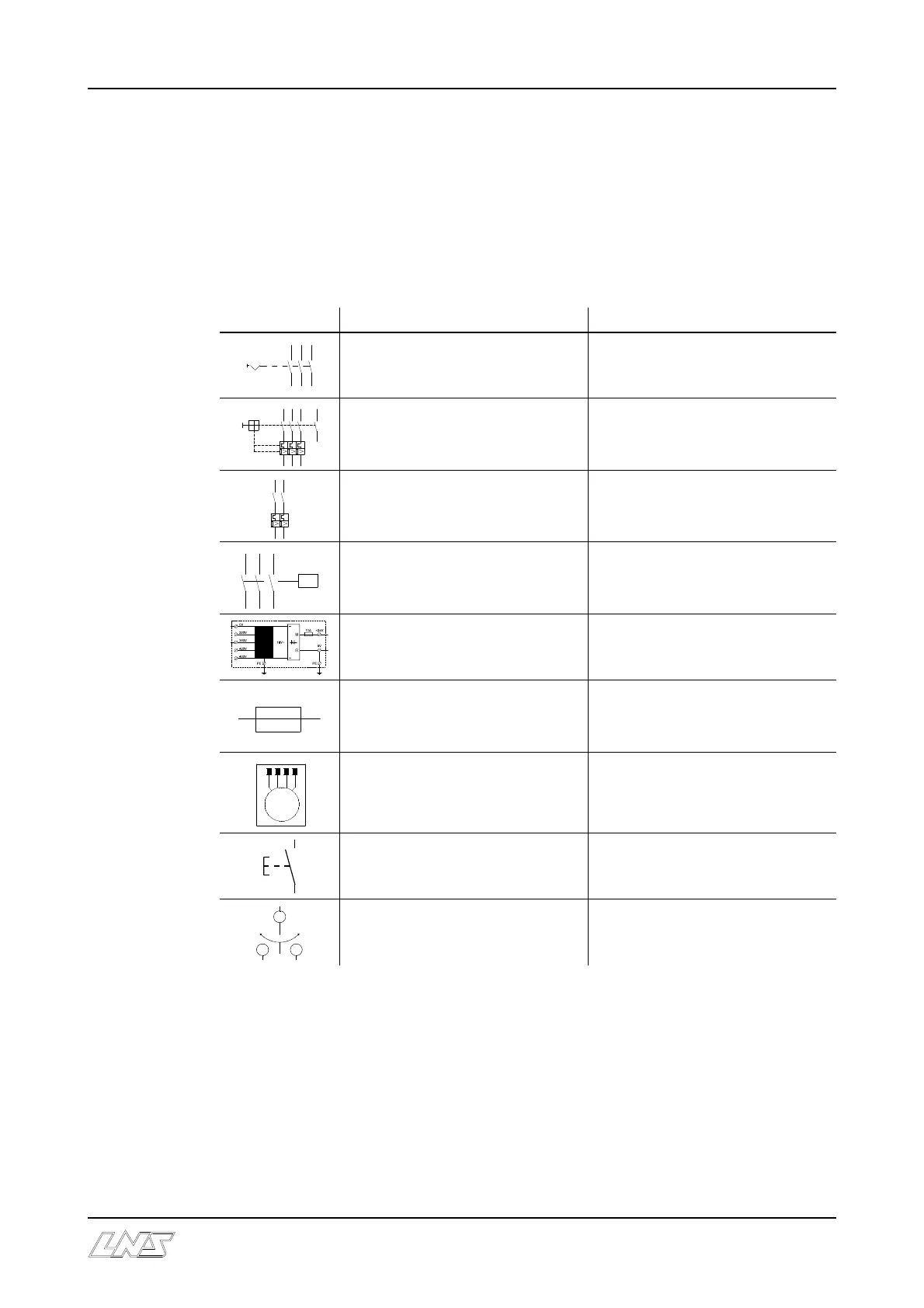
The following table shows the symbols used, as well as their descriptions.
Symbol Description Designation
Main disconnect switch QS1
Main circuit breaker QM1
Circuit-breaker QF1
Contactor mains KM1A / KM1R
Transformer T1
Fuse : 24 V / 5A FU1 / FU2 / FU3
Motors M1 / M2 /M3 / M4
Fixed LOAD control button SB 20
Fixed advance/retract control
button
SB 21 / SB 22