7 - 4 CHAPTER 7 : GENERAL DESCRIPTION
TRYTON 112 CNC
2. CONNECTOR
2.1 Description
When it is not in the barrel (for example when indexing the barrel), the pusher is lodged
in the connector.
The connector block, situated to the rear of the connector, is fed by the hydraulic pump
and feeds hydraulic fluid to the guidance tube as well as advancing the pusher.
When extracting the remnant, the pusher is locked inside the connector block.
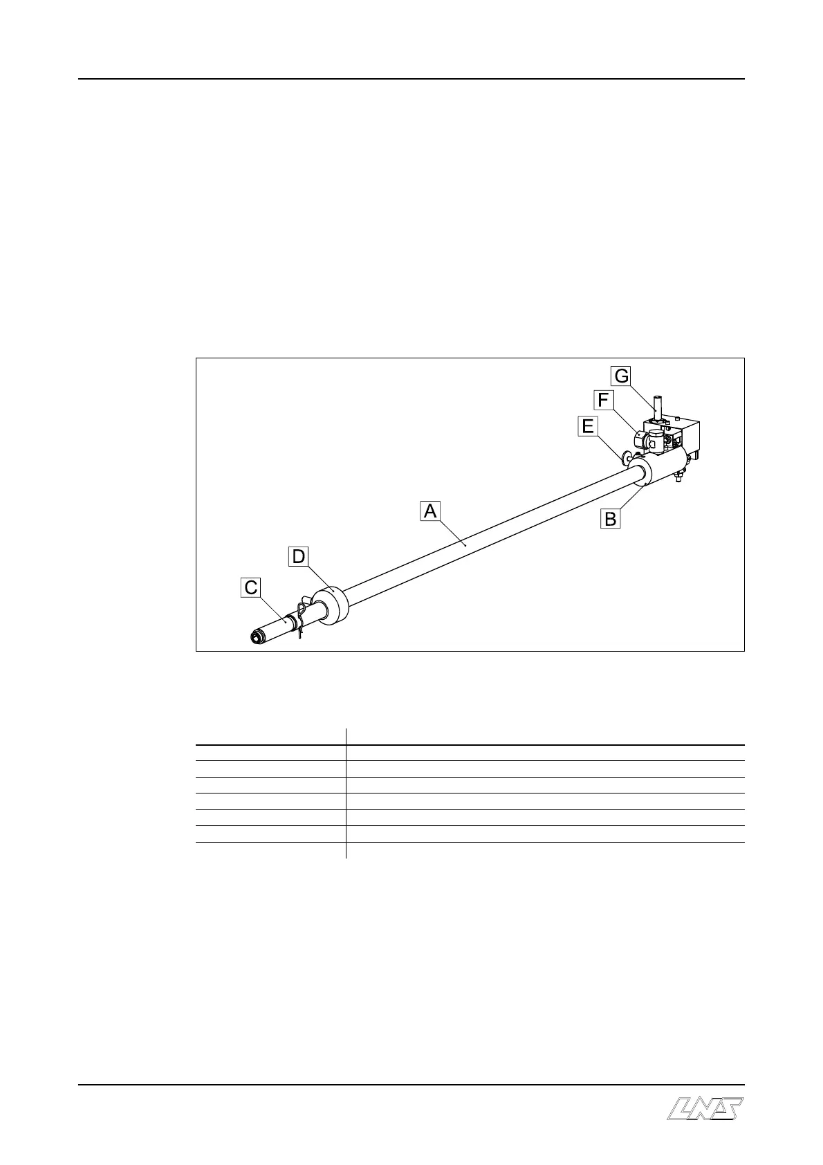
2.2 Layout of the elements
Designation Description
A Connector
B Connector block
C Nozzle
D Cam
E Locking screw
F Hydraulic fluid feed
G Proximity detector : positioning
2.3 Hybrid barrel (option)
Please consult the Start-up Manual for instructions on replacing the connector reduction
tube.