4 - 6 CHAPTER 4: ELECTRICS
TRYTON 112 CNC
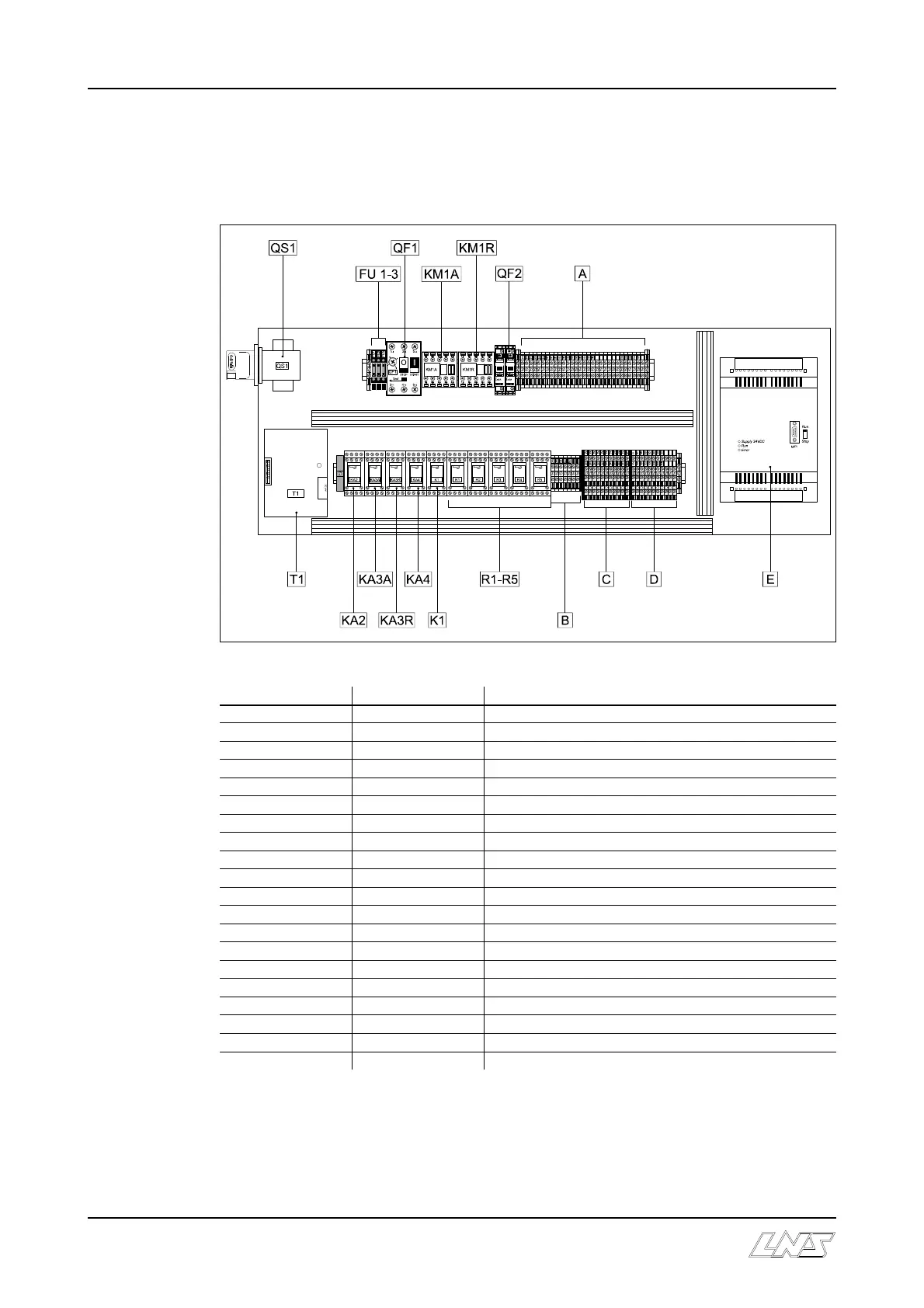
2. ELECTRICAL CONTROL CABINET
2.1 Layout of the elements in the control cabinet
Designation Ordering Nr Description
A 30 x 4.271 Interface connecting terminal blocks
B 7 x 4.271 Safety circuit connecting terminal blocks
C 11 x 4.414 24 Vdc terminal blocks
D 11 x 4.414 Input/output connecting terminal blocks
E 4.559 Programmable controller
FU 1 4.437 Support / fuse 5A
FU 2 4.437 Support / fuse 5A
FU 3 4.437 Support / fuse 5A
K1 4.606 Safety contactor
KA2 4.606 Indexing motor relay
KA3A 4.606 Front connector motor relay
KA3R 4.606 Rear connector motor relay
KA4 4.606 Pusher retract motor relay
KM1A 4.507 Main contactor
KM1R 4.507 Main contactor
QF1 4.503 Main circuit breaker
QF2 4.138 Circuit breaker 2A
QS1 4.242 Main disconnect switch
R1-R5 4.606 Interface relay
T1 4.191 Transformer with 24 Vdc power supply