CHAPTER 3: SETTING INTO OPERATION 3 - 5
TRYTON 112 CNC
Note :
During the
alignment,
ensure that
there is no
reduction unit
in the spindle
(spindle
liner).
Note :
The locking
nuts(A) of the
levellers, must
not be
tightened until
the bar-feeder
has been
anchored to
the ground.
2. MOUNTING
The Tryton 112 bar feed system is delivered completely assembled. Because of this, it is
possible to proceed directly to its alignment when in place behind the lathe.
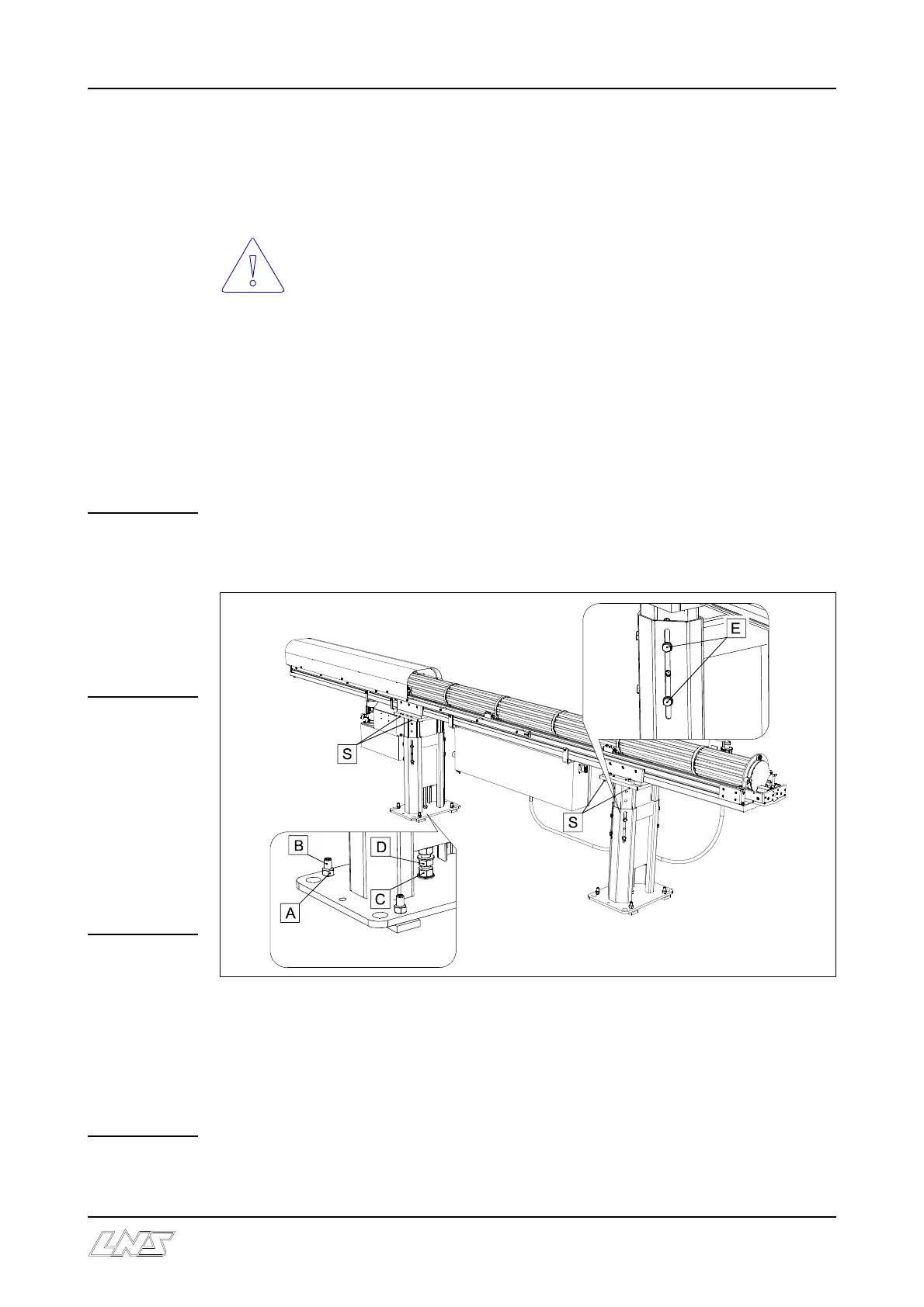
If the bar-feeder is equipped with a lateral pivoting device then, for safety
reasons, the 4 safety screws (S) must not be removed until after the bar-feeder
has been anchored to the ground.
Depending to the type of the lathe, the installation of some adaptation parts is needed
between the lathe and the feeder. Please check with your local LNS agent.
2.1 Alignment
Important : Before proceeding with the alignment of the bar feed system, ensure that
the lathe is stable and preferably leveled.
The alignment may be carried out using a nylon string, an optical tool, etc. If you do not
have any alignment tools, contact LNS or their local representative so they may take care
of the bar feed system installation.
C On each foot, loosen the lock nuts (A) of the leveling screws (B). Then, make sure that
the weight of the bar feed system is evenly distributed over the 8 support points.
C Loosen the lock nuts (D) and make sure that the central screws (C) of the front and rear
feet are supported.
C Loosen the locking screw (E).