CHAPTER 7: GENERAL DESCRIPTION 7-7
ALPHA 552
3. PUSHER
Please read the safety instructions provided at the beginning of this manual before
handling the following devices.
To change the guiding elements and the pusher, the procedure in the start-up manual
must be applied.
3.1. Description
The pusher is used to push the bar stock forward through the spindle of the lathe, until the remaining
material is too short to machine another part. Additionally, depending on the machining process, the
pusher can be equipped to pull back the remnant and evacuate it through the barfeed.
The pusher diameter is 1 mm smaller than the guiding elements’ diameter. This ensures the best bar
guiding.
When the new bar loading cycle is started, one bar is loaded into the guiding zone. The loading flag (A),
which is connected to the servo drive through the chain, moves the bar stock into the spindle. When the
bar is out of interference, the loading flag retracts, the guiding zone closes. The pusher assembly swings
down and connects to the loading flag. The pusher moves forward to finish the bar stock positioning to
the top cut position.
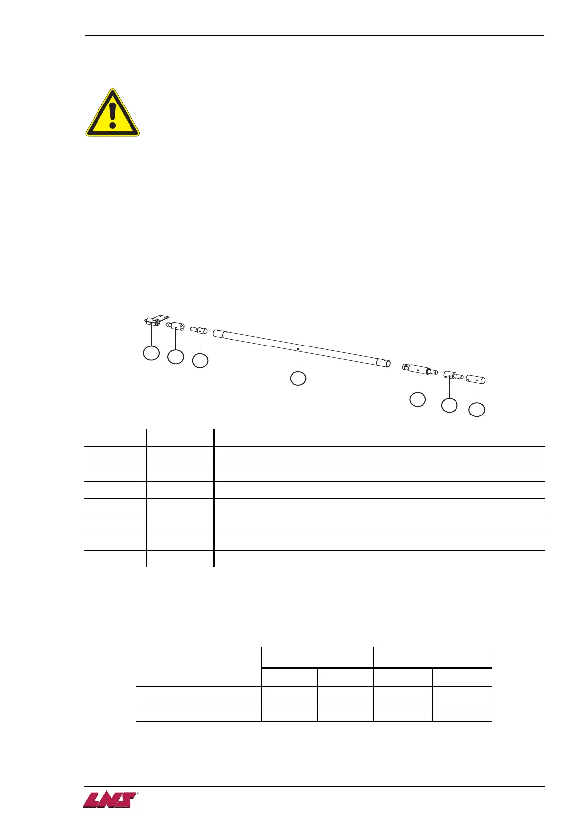
Designation Article No Description
A - Loading flag
B - Connecting part to the loading flag
C - Attach
D - Pusher body
E - Rotating sleeve
F - Adapter (optional)
G - Cone tip or collet
Remnant evacuation:
- Through the lathe : pusher equipped with rotating sleeve and cone tip
- Through the barfeed: pusher equipped with rotating sleeve and collet
Depending on the spindle length, 2 pusher lengths are available:
Pusher version
Pusher length
(LP) ±1
Useable length
(Lu) ±1
Cone Collet Cone Collet
Standard 1596 mm 1554 mm 1220 mm 1178 mm
Long 1876 mm 1834 mm 1500 mm 1458 mm
A
B
C
D
E
F
G