CHAPTER 6: HYDRAULICS 6-3
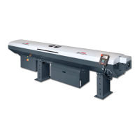
ALPHA 552
2. DESCRIPTION OF THE ELEMENTS
2.1. Hydraulic pump motor
The hydraulic pump is powered by 3 phases 220V AC. The hydraulic pump powers on immediately when
conditions below satisfied:
− The bar feed system switched to automatic mode.
− The guide channel is closed.
− The pusher position is located between home position the “2nd” of parameter P06.
For further information, refer to “Chapter 3. SETTING INTO OPERATION” and “Chapter 4. ELECTRICS”.
2.2. Oil pressure switch
The pressure is constantly monitored by a pressure
switch set at the factory at a point of release of 0.5
bar. It may be adjusted, if necessary, as follows :
Settings:
1. With a screwdriver, unscrew the locking
screw (A).
2. Insert a hex head wrench (5mm) into the
center of the pressure switch (B).
By turning clockwise, the release of the
pressure switch will take place at a pressure
higher than the original setting. Turning in the
opposite direction, will produce the reverse.
3. When the adjustment is completed, retighten
the locking screw (A).
2.3. Filling and draining
The barfeed system is delivered without oil. 50 litres (14 gallons) of hydraulic oil of the type indicated
below must be provided by the client. The oil must be poured directly into the machine. The oil height
should be kept around H mark on the level when the hydraulic pump is not running.
Viscosity equivalency table
ISO 100 100 mm2/s (cSt) at 40°C DIN 68 8°E to 50°C
Consult your supplier who will recommend the correct oil for you.
A thicker oil (ISO 150) may, in certain cases, produce better results when guiding profiled
bars.
+
-
A
B
SP2