7-4 CHAPTER 7: GENERAL DESCRIPTION
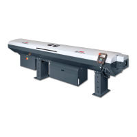
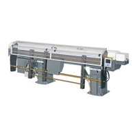
ALPHA 552
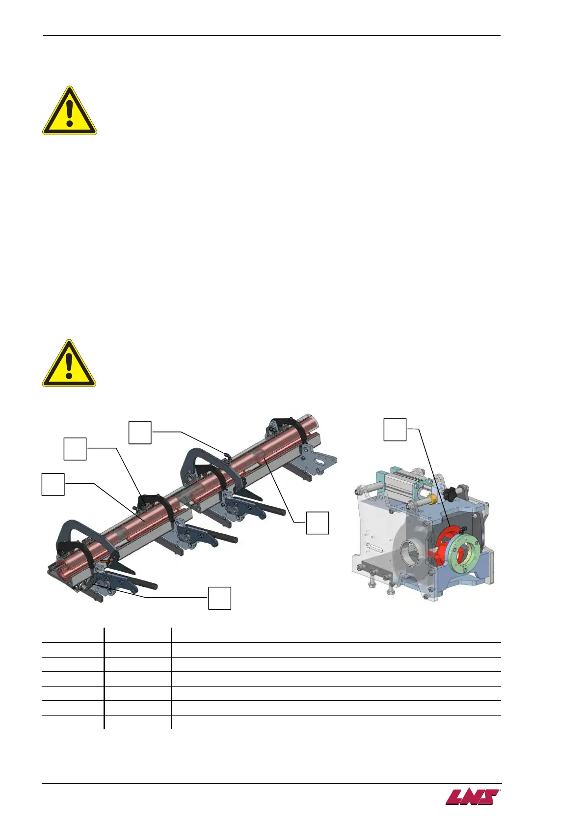
2. GUIDING ELEMENTS
Please read the safety instructions provided at the beginning of this manual before
handling the following devices.
2.1. Description
The guiding zone consists of a fixed lower aluminium profile, and a movable upper aluminium cover.
Located in the guiding zone, the guiding elements act as supports for the bar stock by reducing the
clearance, and dampen the vibration due to their special rubber material. Sets of guiding elements of
different diameters are available to adapt the barfeed to the bar stock. The best guiding quality is
determined by guiding elements 1 mm bigger than bar stock diameter.
When the new bar loading cycle is started, the guiding zone opens; one bar is loaded into the guiding
zone. The bar is pushed into the spindle, then the system closes and is locked in closed position. The
system will remain until a remnant is evacuated, or a new bar is loaded.
Hydraulic oil is injected through the upper supports and distributed all along the bar stock. An oil bath is
created around the rotating bar, inducing a hydrodynamic effect which keeps the bar stock at the center
of the guiding axis, dampens the vibration, and reduces friction heat.
The guiding channels are sensitive to corrosive products. Please do not wipe or clean the
channels with any corrosive detergent. Use a dry cloth only to wipe the oil off the channels.
2.2. Layout of the elements (*)
Designation Article No Description
A - Upper guiding element
B - "Quick Change" holding system for the upper guiding elements
C - Oil supply
D - Lower guiding element
E - Locking system
F -* Front rest guiding elements*
(*) Some elements are explained in more details in the following paragraphs.
A
D
E
C
F
B