4-10 CHAPTER 4: ELECTRICS
ALPHA 552
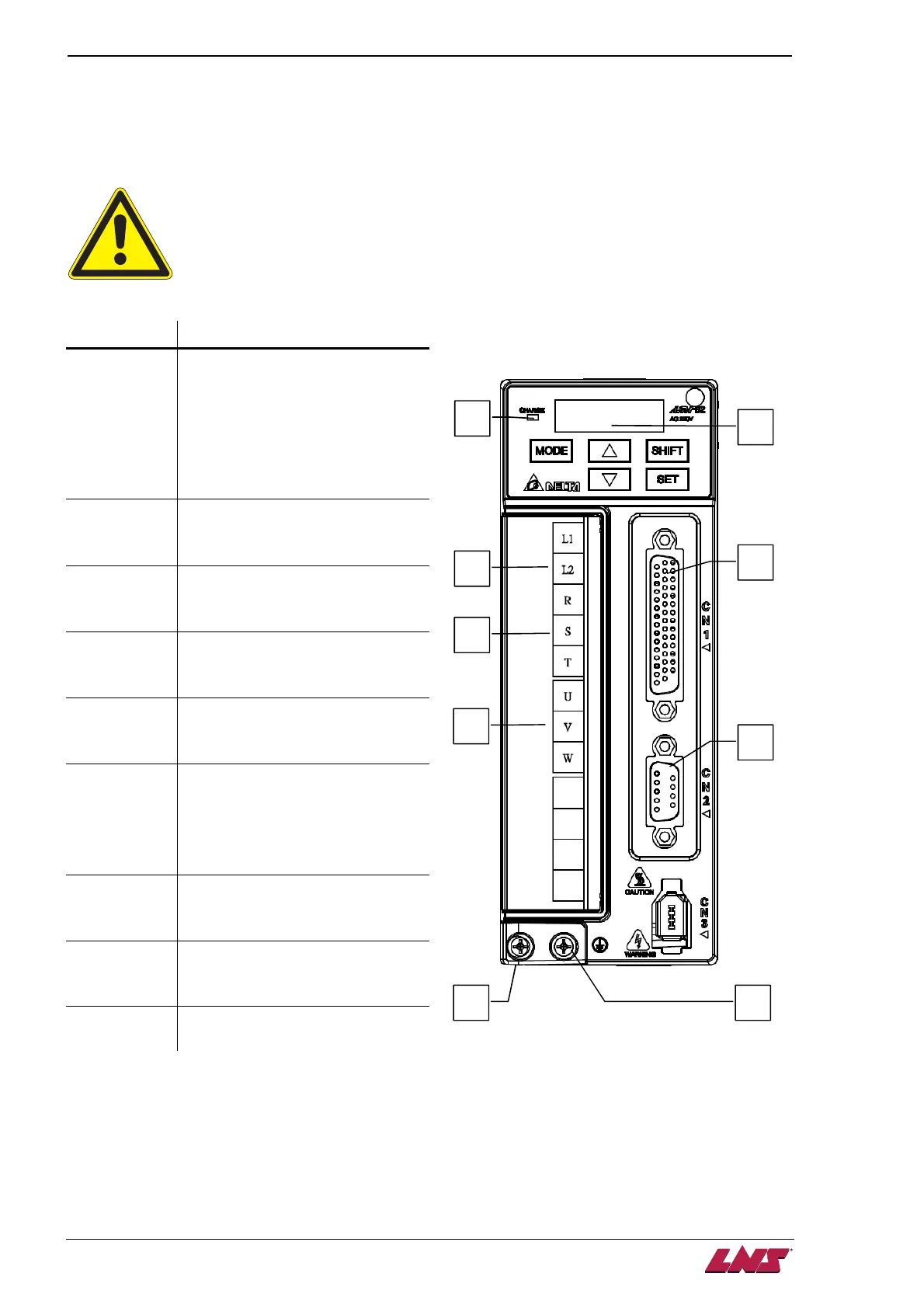
2.2.7. Servo amplifier
By means of the SERVO amplifier, the programmable controller controls the movements of the motor.
The input values, as well as the position of the pusher carrier, are continuously registered. The values are
saved by means of a battery. Therefore, the axles do not need to be placed at zero when the barfeed
system is powered up.
Ensure that the emergency stop equipment or device is connected and working
correctly before operating the motor that is connected to a mechanical system.
Designation Description
A
Charge LED
A lit LED indicates that either power is
connected to the servo drive OR a
residual charge is present in the
drive’s internal power components.
DO NOT TOUCH ANY ELECTRICAL
CONNECTIONS WHILE THIS LED IS
LIT.
B
LED display
Displays the servo status or fault
codes.
C
Control circuit terminal (L1, L2)
Used to connect 200 – 230 VAC,
50/60Hz single-phase power supply.
D
Main circuit terminal (R, S, T)
Used to connect 200 – 230 VAC,
50/60Hz commercial power supply.
E
Servo motor output (U, V, W)
Used to connect the servo motor.
F
Heatsink
Used to secure servo drive and for
heat dissipation.
DO NOT TOUCH, MAY BE VERY
HOT AND CAUSE SERIOUS
PERSONNEL INJURY.
G
I/O interface (CN1)
Used to connect host controller (PLC)
or control I/O signal.
H
Serial communication interface
(CN2)
Used to connect other controllers
I
Ground terminal
B
A
C
D
E
G
F
H
I