10
CONTROL PANEL
CONTROL PANEL
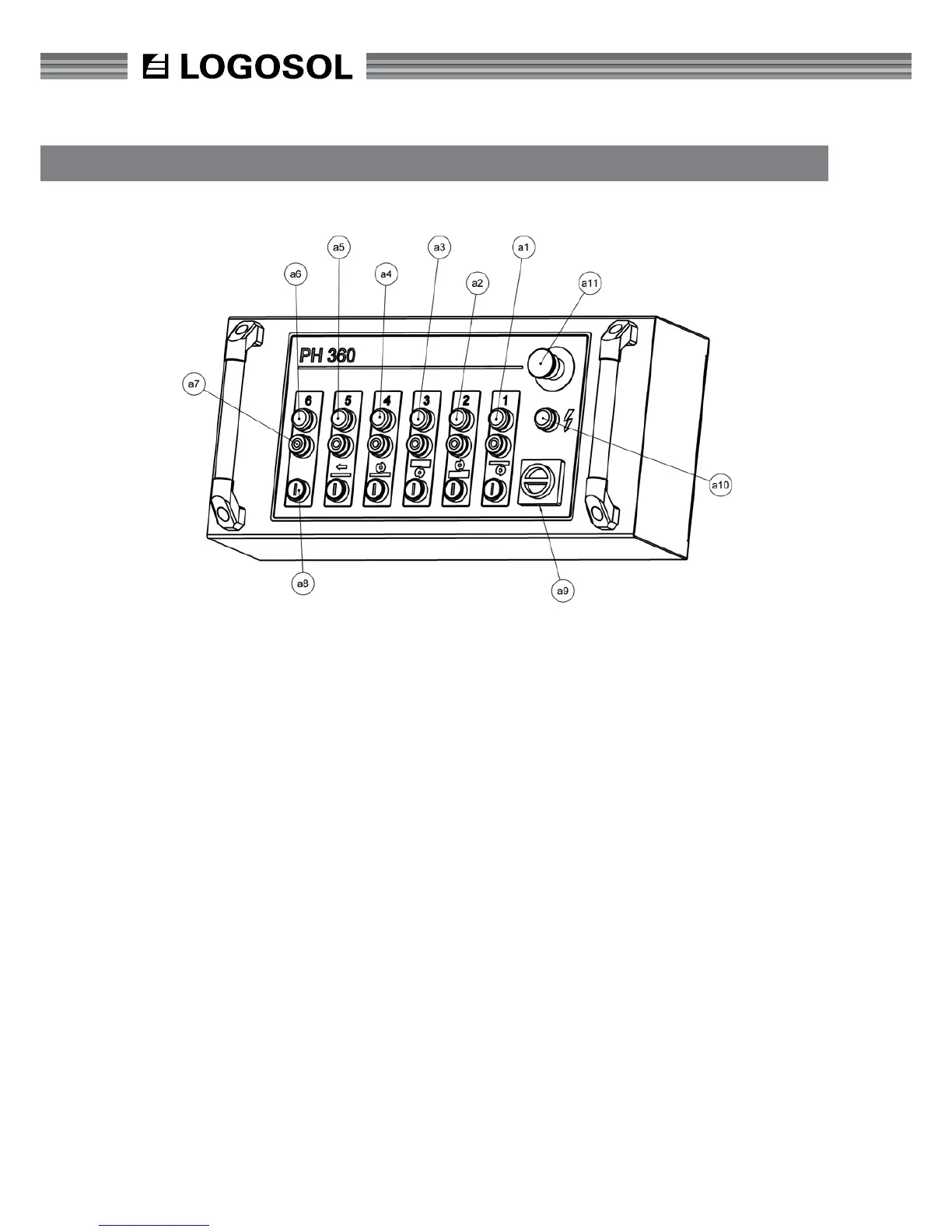
The top red button (a11) is the emergency stop and
switches off the power to all functions. When the
emergency stop is used, it must be pulled out again
in order for the planer/moulder to be re-started.
Under the emergency stop is a light (a10) which
indicates that the power supply is connected. When
replacing knives and during servicing, for example,
the power switch (a9) must be in the off position.
Check that the light (a10) is not lit.
The bottom black row of buttons (a8) start the
planer's motors. The top red row of buttons (a7)
stops the planer's motors (a7). Above each button
there is a light (a6) which indicates that the relevant
motor is running.
The button's function is from the right:
1. Starting the planer cutter (lower horizontal cutter)
2. Starting the side cutter, right
3. Starting the side cutter, left
4. Starting the planer cutter (upper horizontal cutter)
5. Starting the feed
6. To control extra motors, or a fth cutter