EasyManua.ls Logo

Logosol PH360 - Machine Setup and Preparations; Assembly and Initial Setup Steps

Logosol PH360
44 pages
Print Icon
To Next Page IconTo Next Page
To Previous Page IconTo Previous Page
Loading...
7
LOGOSOL PH360
PREPARATIONS
Certain parts are not assembled on delivery for
transport and packaging reasons.
1. Assemble the control panel in place with the
arm where the cabling goes, (232), (251).
2. Assemble all safety doors.
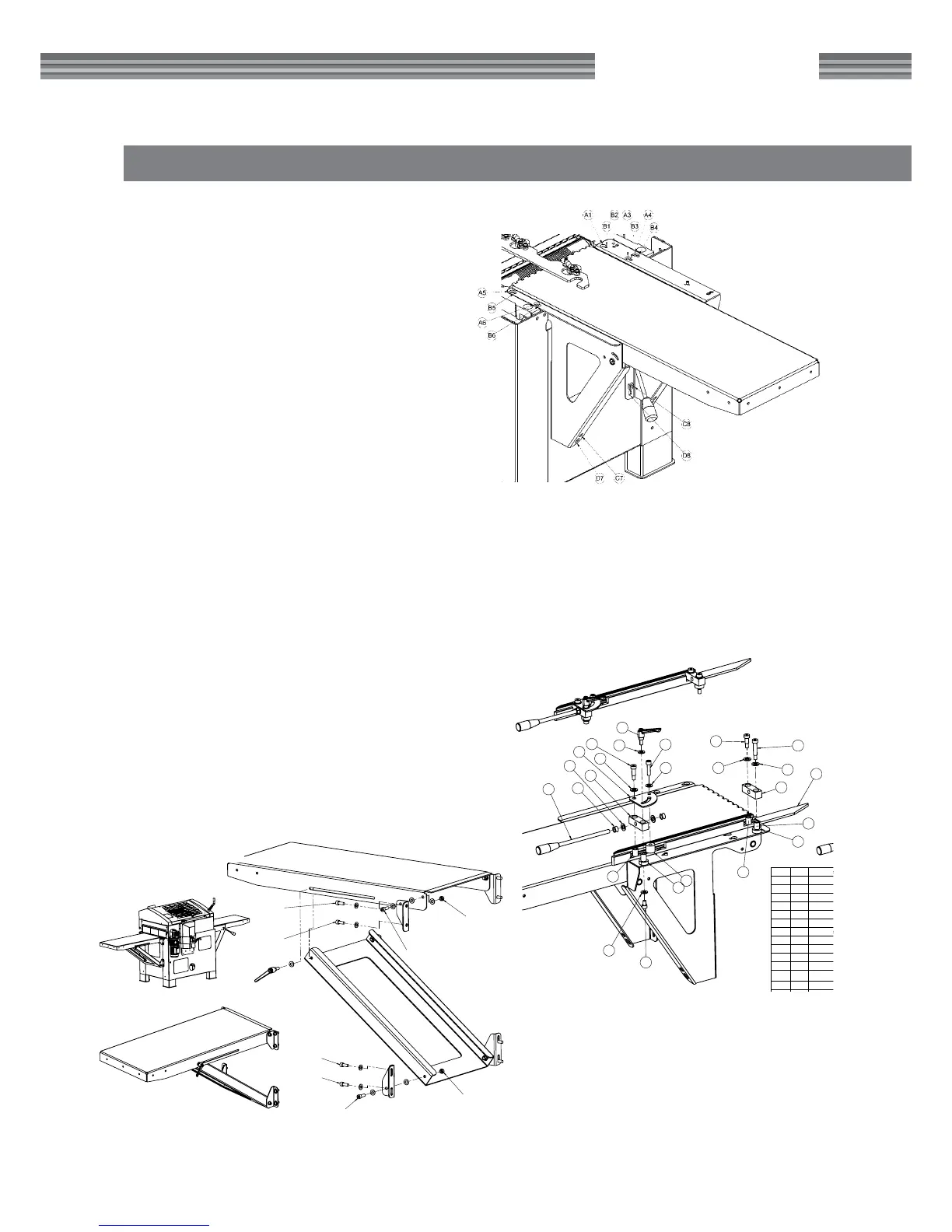
3. Assemble the infeed table (212). [Figure 1]
• Screw down all adjustable screws (B) in the
bottom.
• Insert all screws (A) tighten by hand.
• Insert the adjustment screws (C) and adjust
the table so it is straight.
• Adjust exactly: The highest position of the
infeed table must be on the same level as the
cast machine table. Check with a long, straight
fence rail.
• Adjust the height of the table so that it
touches the cast iron table with the adjustment
screws (B) and tighten the holding screws (A).
• Check the table angle and table height and
insert the table xture’s bottom lock screws (D)
which are fastened using nuts on the inside of
the chassis.
4. Assemble the outfeed table (253). [Figure 2]
5. Assemble the side fences [Figure 3]
6. Connect the planer/moulder to the chip extrac-
tor.
7. Before the planer/moulder is connected to the
electrical circuit, check that all cutters can rotate
freely, and that all parts are xed.
Hole pattern key:
A: Holding screws for the infeed table.
B: Holes for accessing the adjusting screws where the screw
head lies under the table xture.
C: Threaded hole for adjustment screws for setting the table angle.
D: Hole for lock screws.
E: Fixing point for adjustable side fence. A double hole pattern
means that the fence can be placed in an outer or inner position
Figure 1.
PH360
M10-30mm
M10-25mm
M10-25mm
M10-30mm
M10
M10
M10-25mm
M10-25mm
19
39
27
16
14
38
22
22
22
43
42
13
23
15
17
16
14
24
16
25
42
41
26
42
16
Nr.
Antal
Benämning Material
Dimension
Anmärkning
43 1
Insex M10 15mm
42 3
Bricka 10,8x22x2
Stål Blankförzinkad
Bricka 11x22x3
41 1
Lever-GN300-S78-Wiberger
40 1
Tap-GN30078-M10x20-Wiberger
39 1
Passkruv ISO7379 d12 L45 M10
38 1
Distans bussning
Automatstål
Stång D30 L11
360-342
27 1
Passkruv ISO7379 d12 L20 M10
26 1
Insex M10 40mm
25 1
Passkruv ISO7379 d12 L25 M10
24 1
Annhåll låsplåt
1312
Plåt 4mm
360-167-2
23 1
Annhåll låsplåt Distans bussning
Automatstål
Stång D30 L25
360-134-1
22 3
Fästbusning annhåll
Oljebrons
Lager d12 D18 L25
360-125-1
19 1
Annhåll profil 3
AL
AL-profil:360-325
40x30x800
360-329
17 2
Mutter M12
16 5
Bricka 13x24x2
Stål Blankförzinkad
Bricka 11x22x3
15 1
Annhåll justerspak
14 2
Länkarm inmatning
Automatstål
Plattstång 25x25 L80
360-142-3
13 2
Fäste länkarm
Automatstål
Stång D30 L36
360-124-3
1 av 1
Blad.
_
2010-11-15
_
_
1:20
_
_
_
MK
_
Ritn.-nr
Dat.
Ersatt av
Ersätter
Skala
Godk.
Stand.
Kontr.
Kop.
Ritad
Konstr.
MOReTENs
Matarbord Ass
360-277
Figure 2.
19
39
27
16
14
38
22
22
22
43
42
13
23
15
17
16
14
24
16
25
42
41
26
42
16
Nr.
Antal
Benämning Material
Dimension
Anmärkning
43 1
Insex M10 15mm
42 3
Bricka 10,8x22x2
Stål Blankförzinkad
Bricka 11x22x3
41 1
Lever-GN300-S78-Wiberger
40 1
Tap-GN30078-M10x20-Wiberger
39 1
Passkruv ISO7379 d12 L45 M10
38 1
Distans bussning
Automatstål
Stång D30 L11
360-342
27 1
Passkruv ISO7379 d12 L20 M10
26 1
Insex M10 40mm
25 1
Passkruv ISO7379 d12 L25 M10
24 1
Annhåll låsplåt
1312
Plåt 4mm
360-167-2
23 1
Annhåll låsplåt Distans bussning
Automatstål
Stång D30 L25
360-134-1
22 3
Fästbusning annhåll
Oljebrons
Lager d12 D18 L25
360-125-1
19 1
Annhåll profil 3
AL
AL-profil:360-325
40x30x800
360-329
17 2
Mutter M12
16 5
Bricka 13x24x2
Stål Blankförzinkad
Bricka 11x22x3
15 1
Annhåll justerspak
14 2
Länkarm inmatning
Automatstål
Plattstång 25x25 L80
360-142-3
13 2
Fäste länkarm
Automatstål
Stång D30 L36
360-124-3
1 av 1
Blad.
_
2010-11-15
_
_
1:20
_
_
_
MK
_
Ritn.-nr
Dat.
Ersatt av
Ersätter
Skala
Godk.
Stand.
Kontr.
Kop.
Ritad
Konstr.
MOReTENs
Matarbord Ass
360-277
Figure 3.

Related product manuals