TOP CUTTER
Before you open the safety doors on the
planer, ensure that the power is switched
off and that the cutters are not rotating. Use
protective gloves, particularly when you need
to loosen screws that are tightly fastened, or
when you are tightening screws (see safety
instructions). Beware of the planer knives. It is
extremely easy to cut yourself on these, even
with the slightest touch.
SETTING THE CUT OF THE TOP CUTTER
The planer thickness is set using the planing table
crank (189). The set thickness can be read on the
indicator (109) on the machine stand. The indicator
can be calibrated. Plane some wood and adjust the
top cutter until you get the correct height. Release
the green cover (168). The ring above the indicator
has a stop screw. Turn the ring so that it shows the
planing height that has been planed.
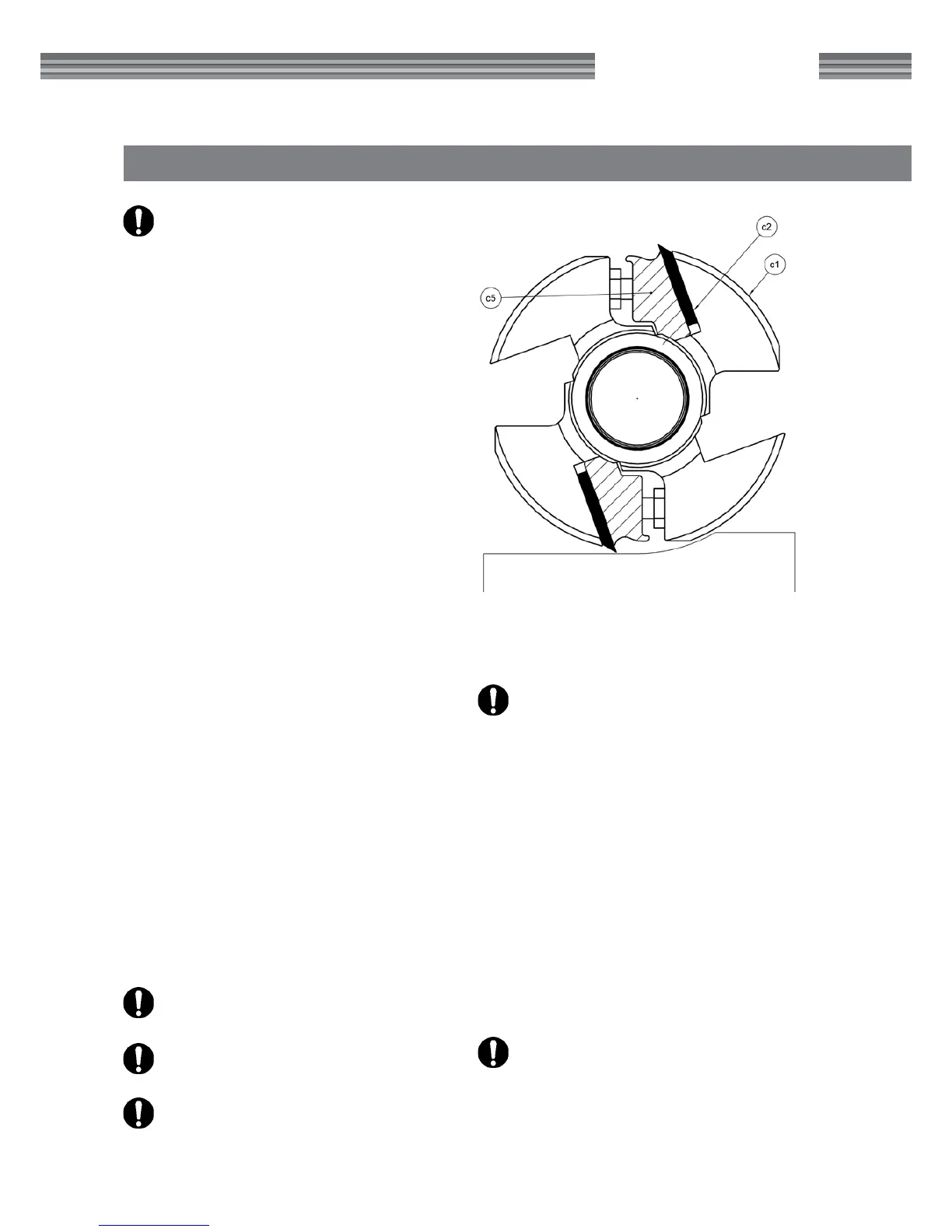
The top cutter is xed to the chassis and hung at
both ends. Two planing knives are mounted in two of
the bottom cutter's tooling slots on delivery (planer
knife 510 mm (20") HSS, item no. 7000-002-8510).
Another two planing knives, or molding knives can be
mounted in the two empty tooling slots.
Always set the top cutter uppermost to reduce any
slack in the threads. If the top cutter needs to be
lowered, lower it half a rotation too low and then
raise it into the correct position. Once you have the
top cutter set at the correct height, you can lock it
in position with the handle to the right of the feed
motor assembly.
DISASSEMBLING, ASSEMBLING AND
GRINDING PLANING KNIVES
See above, under the Bottom cutter section. Exceptions:
The minimum height of the planing knifes are different.
Make sure you´re using the right Setting Block.
After adjusting or replacing planing knives:
Check that no tools have been left in
the planer.
Check that all screws have been sufciently
tightened.
Check that the cutters can rotate freely before
the safety doors are closed.
Do you remember the warning instructions on
pages 4-5?
ADJUSTING PLANING KNIVES
Adjust the planing knives so that they are the same
level and protrude 1 mm (.040"). This is done using
an aluminum adjustment block (item no. 7500-000-
1020), found in the component packaging on the
planer table when the planer/moulder is delivered.
Loosen the chip breaker's lock screws slightly, and
place the adjustment block over the knife. Adjust
the knife up or down until the knife brushes against
the block when it passes above the knife. (The pla-
ning knife protrusion can also be adjusted using a
magnetic adjuster for the top cutter, item no. 7500-
001-0050. See the instructions enclosed with the
magnetic adjuster.)
Tighten the lock screws that lock the knife,
counter-clockwise. Start by tightening care-
fully. Move from the sides in move towards the
middle, retightening them later.