16
SIDE CUTTERS
Before you open the safety doors on the
planer, ensure that the power is switched
off and that the cutters are not rotating. Use
protective gloves, particularly when you need
to loosen screws that are tightly fastened, or
when you are tightening screws (see warning
instructions).
The side cutters are xed to the planer table. The
spindles are 30 mm (1 2/10") in diameter, which is
a standard measurement. Upon delivery, the planer
is equipped with two universal cutters with planing
knives, which you can easily replace with molding
knives. For reasons of safety, the cutters work with
conventional milling (the workpiece is fed towards
the molder's cutting motion). This means that the
lock nut and spindle on the moving side cutter must
be left-hand threaded.
The moveable side cutter's lock nut is left-
hand threaded.
After assembling the molding knives:
Check that no tools have been left in the planer.
Check that all screws have been sufciently
tightened.
Check that the cutters can rotate freely before
the safety doors are closed.
Do you remember the warning instructions on
pages 4–5?
DISASSEMBLING
Cutter 2 (Right, xed cutters): Loosen the nut on
the spindle with a 30 mm wrench (supplied) and
a 1/2” or 13 mm wrench or adjustable wrench.
Unscrew the nut and remove the cutter (A) and any
spacing rings under the cutter.
Cutter 3 (left, moveable cutters): Crank the cut-
ters to their previous position. The nut is loosened
in the same way as for cutter 2, with the difference
that the nut for cutter 3 is left-hand threaded and is
therefore screwed in the opposite direction.
TIP: The side cutter nuts are loosened by turning them
in the same direction as their respective cutter rotates.
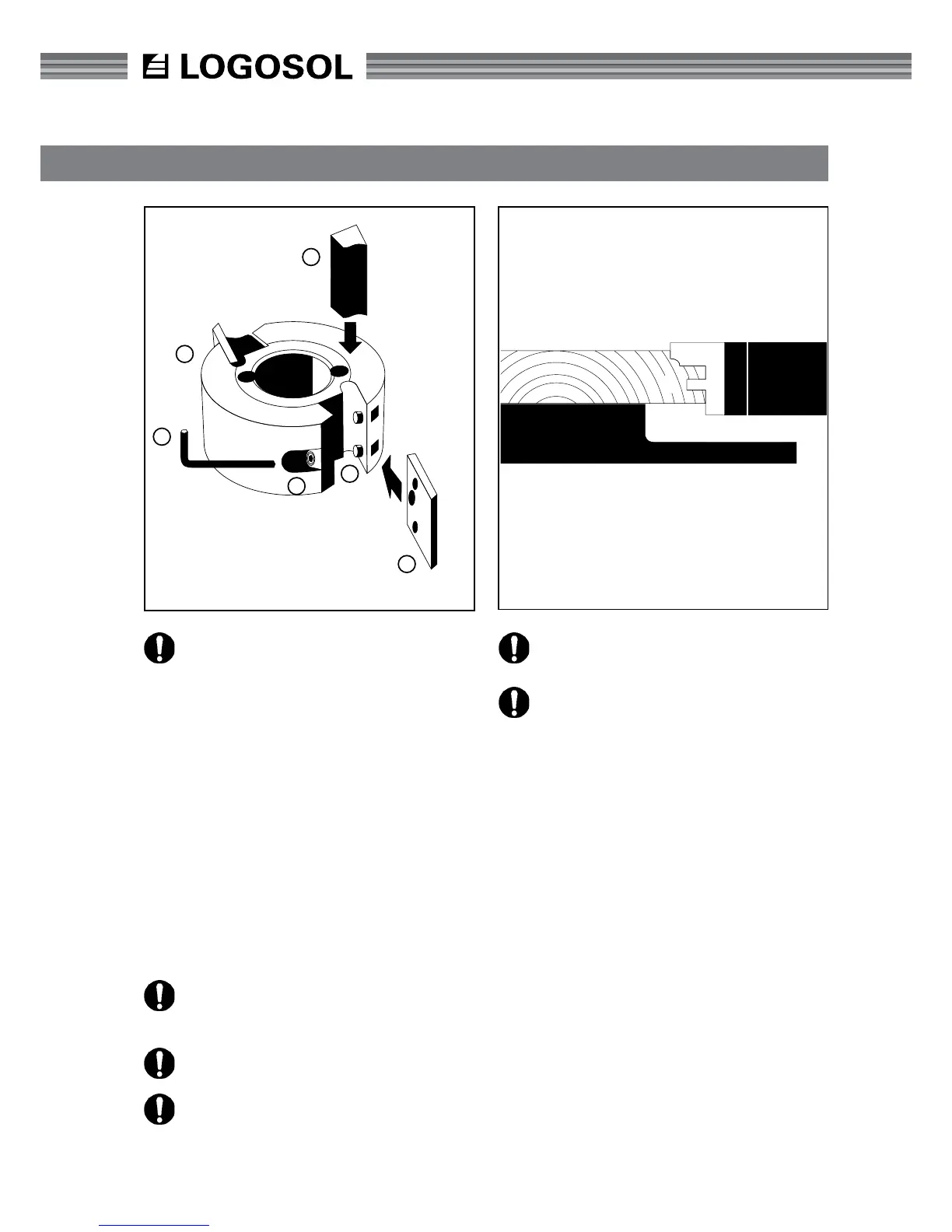
REPLACING KNIVES
Loosen the lock screw (B) with a 4 mm Allen wrench
(C) (supplied) and remove the chip breaker (D). Then
remove the knife (E) from the peg (F). Insert a new
wrench and tighten the locking screw tightly.
C
A
D
B
F
E
6
7
8