6
TOOLS REQUIRED
A LIST OF THE TOOLS REQUIRED TO BE ABLE
TO WORK WITH THE PLANER/MOULDER:
Allen key 4 mm (supplied)
Allen key 5 mm
Allen key 6 mm
Open ended wrench 10 mm (supplied)
Wrench 10 mm
Ring wrench 13 mm
Open ended wrench 30 mm (supplied)
(for milling spindle)
Adjustable wrench 8" or 10"
(for milling spindle)
Sliding caliper
Measuring tape or ruler
Parafn oil for the table
Whetstone
THE FOLLOWING SPACER RINGERS ARE
SUPPLIED:
3 x 40 mm height
2 x 20 mm height
2 x 10 mm height
1 x 5 mm height
2 x 2 mm height
1 x 1 mm height
1 x 0.5 mm height
1 x 0.3 mm height
1 x 0.2 mm height
1 x 0.1 mm height per cutter
These spacer rings allow you to set the required height.
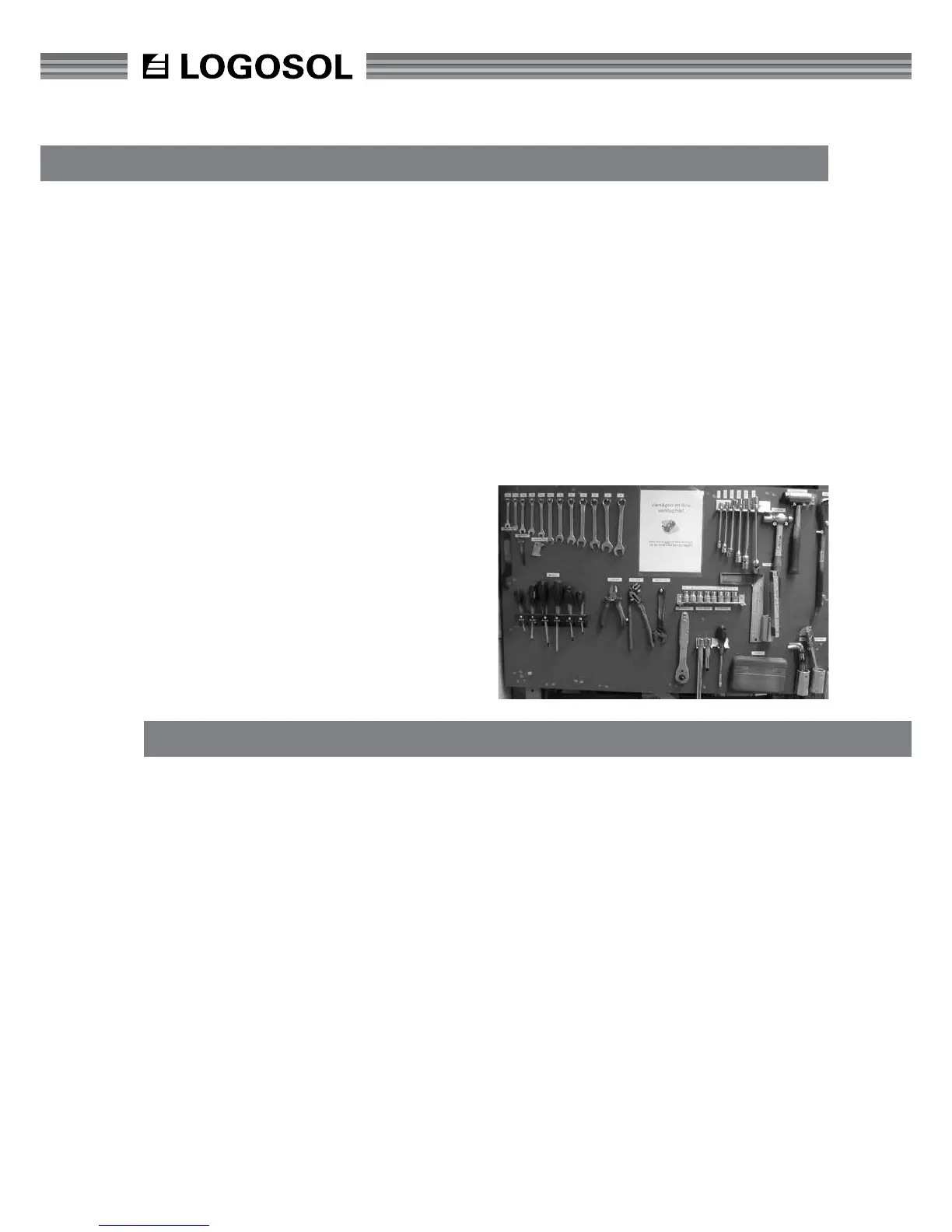
Tips! Make a tool board with the tools you
need, and position it next to the planer/moulder
so that you can see it easily. Look at the tool
board before you start the planer/moulder to
see if any tools are missing. They could have
been left in the planer/moulder!
MACHINE DESCRIPTION
The PH360 is a planer/moulder that can work four
sides of a workpiece in one action. The planer/moul-
der is contained in a stable and strong chassis. The
planer/moulder table and slide for the moving cutter
are made of planed cast iron.
The workpiece is fed, lying on the planer table,
through the planer by four feed rollers as well as
an outfeed roller. The rollers are driven by a chain
transmission with separate motor. The workpiece is
controlled laterally with adjustable fences and pres-
sure rollers.
The work is done using a top cutter and a bottom
cutter, that are hung at both ends, as well as two
side cutters which are xed to the planer table. All
the cutters are driven by separate motors, via a belt
transmission.
The cutters and feed rollers are covered by a folda-
ble protective cover plate with window. The cover
plate is supplied with a safety switch. Another safety
switch sits behind the top edge of the cover plate on
the infeed side. A 100 mm (4”) hose is connected
to the bottom and side cutters and a 125 mm (5”)
hose is connected to the top cutter with the option
of an additional 100 mm (4”) for connection to the
chip extractor.
TABLE SURFACE
The table is cast in the highest quality. The table sur-
face is specially processed for the highest precision
and the best anti-friction qualities. When the planer/
moulder is new, it requires a driving-in period until
the table gets a slightly shinier surface to optimize
the anti-friction qualities. During this period, we
recommend that you use a lubricant or wax on the
table.