18
ADJUSTING THE FENCE BY CUTTER 2
In general
The front side fence has a double set of holes for
assembly. It can therefore be assembled in two
basic positions. When the TB90 system is used, the
fence will be tted in the pair of holes on the right,
as seen from the infeed side (see assembly of side
fence, page 7). When cutters with larger diameters
are used, the fence can be moved to the left pair of
holes, so that the stroke length is sufcient.
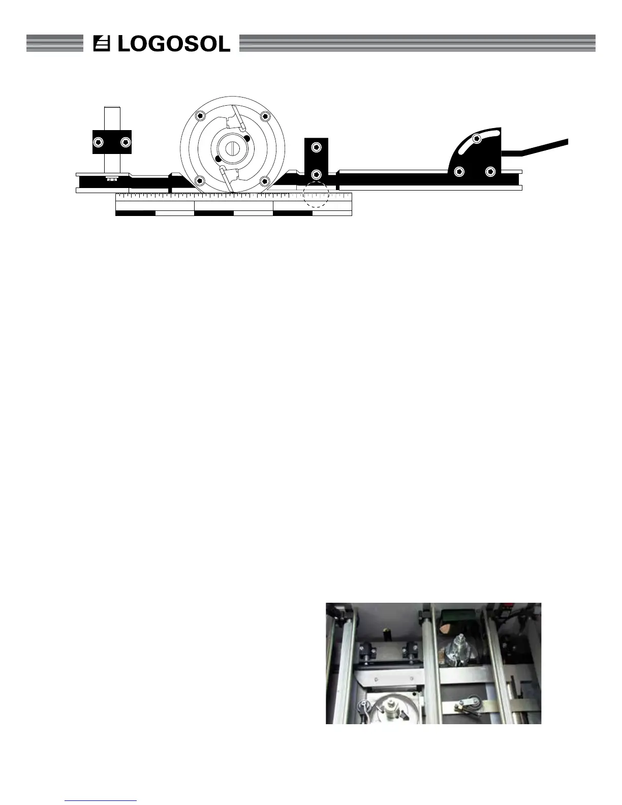
The xed cutter has two fences, the front (62) and
the back fence (54). The front fence controls how
much the cutter cuts, and the back fence works as a
support for the workpiece when it has passed cutter
2 and is ready to be worked by cutter 3.
Both fences must be in line with one another, but
offset in parallel so that the front fence is slightly
more to the right (see g.). In this way, the back
fence will support the workpiece once it has been
cut by cutter 2 (the workpiece is slightly smaller then).
The fence is xed by socket head screws in the fence
holders (55) according to g. The screws that lock the
fence in the horizontal direction are 13 mm (5/10")
hexagonal screws and sit in the fence's U prole. In
addition, there are micro adjustments on the fence.
When the hexagonal screws are loosened slightly,
the knob for micro-adjustments can be turned. If the
angle of the fence needs to be adjusted, both the
hexagonal and socket head screws must be loosened.
INSTALLATION OF SIDE FENCES
Method 1:
• Insert the rst fence inwards, for minimal cut-
ting. Add a straight aluminum fence rail tight
against the fence. Adjust the fence using the le-
ver until the loose fence rail touches the cutter’s
plane diameter (the outer rotating line) as it lies
against the rst fence.
• The plane diameter that is inline with the back
fence is where you need to measure to, the
cutter’s plane diameter that is higher than 30
mm above the table height is unimportant here.
• Align the back fence along the guard rail, which
is still tight against the rst fence and tighten it.
The cut is now 0 mm. The rst fence, cutter and
back fence are fully inline, and the rst fence
controls the angle through the machine.
• Remove the fence rail and all loose tools from
the machine.
• Move the rst fence back to the required cut
and lock it using the tie-back knob. (Around 2
mm is usually a suitable cut for the rst cutter.)
Method 2:
• The back fence is pulled in so that it is not used,
and is xed there. (Check that the cutter can
rotate freely.)
• Position the front fence so that the required cut
depth is obtained and the fence stands straight.
Tighten the screws that x the fence.
• Close the safety doors and take the measures
required to start the planer/moulder (see page 4).
• Start the bottom cutter, both side cutters and
the feeder and feed in a test piece of approx. 1
meter (3 ft). Stop the planer/moulder just as the
board reaches the moveable cutter (cutter 3).
• Drive the back fence towards the planed part of
the board.
• Check that the test piece is lying against both
Installation jig for adjusting fences.