Basic Setup (LHV2000 Series)
6
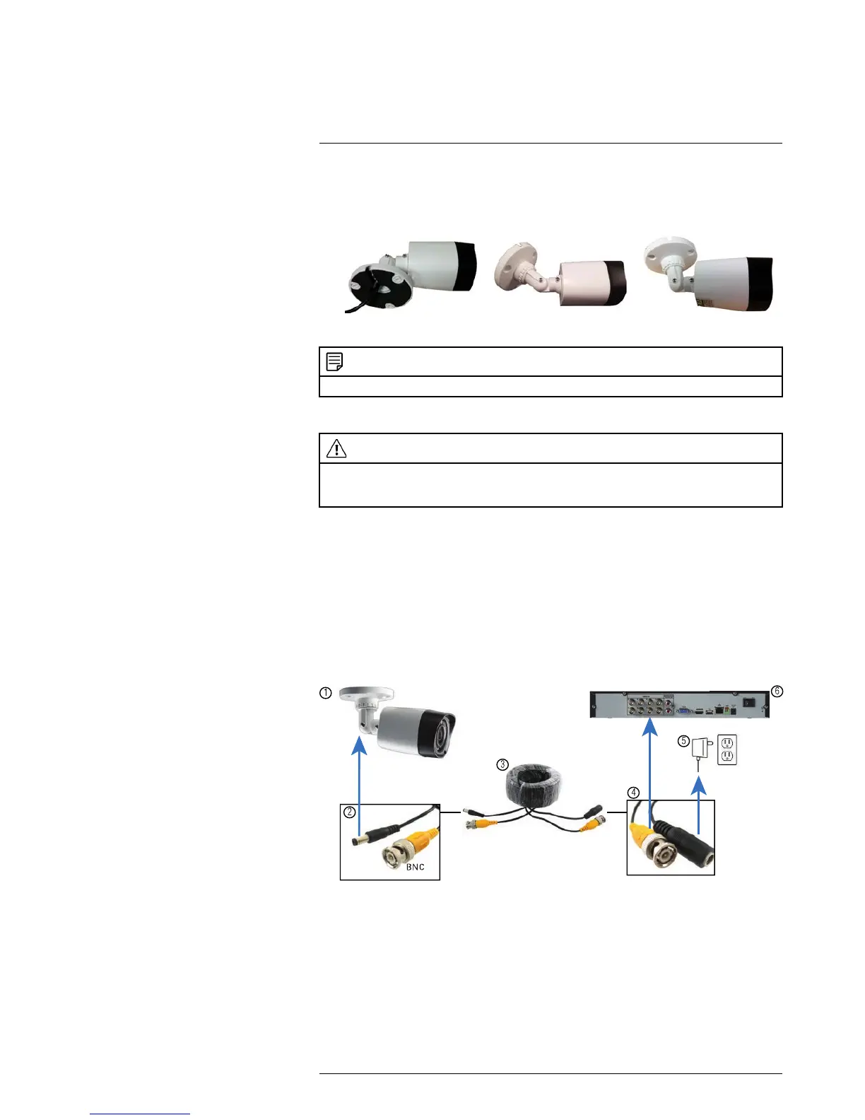
2. Adjust the camera stand to ensure that the camera has a satisfactory view of the area
you would like to monitor. Stand configuration depends on the mounting surface you
have chosen (see below for suggested stand configurations).
Table Mount Wall Mount
Ceiling Mount
NOTE
Camera model may not be exactly as shown.
6.11.4 Connecting Camera Extension Cables
CAUTION
The extension cable must be a single stretch of cable between the DVR and camera. You cannot con-
nect multiple extension cables to each other. For more details on extension cables, see 6.11.5 Exten-
sion Cable Options, page 15.
1. Connect the male power connector on the BNC extension cable to the female power
connector on the camera.
• Connect the BNC connector to the camera.
2. Connect the female power connector on the BNC extension cable to the power
adapter.
3. Connect the BNC connector to one of the Video Input ports on the rear panel of the
DVR.
4. Plug the camera power adapter to a power outlet.
Camera Installation Diagram
1. Camera.
2. End of extension cable with male power connector.
3. Extension cable.
4. End of extension cable with female power connector.
5. Camera power adapter.
6. DVR.
6.11.4.1 Connecting and Removing BNC Cables
BNC (Bayonet Nut Connector) is a special connector that locks on to the system port
and cannot be accidently removed.
#LX400060; r.30328/35049; en-US
14
 Loading...