ASSEMBLY
OM 0467SB-A [18]
Step 5
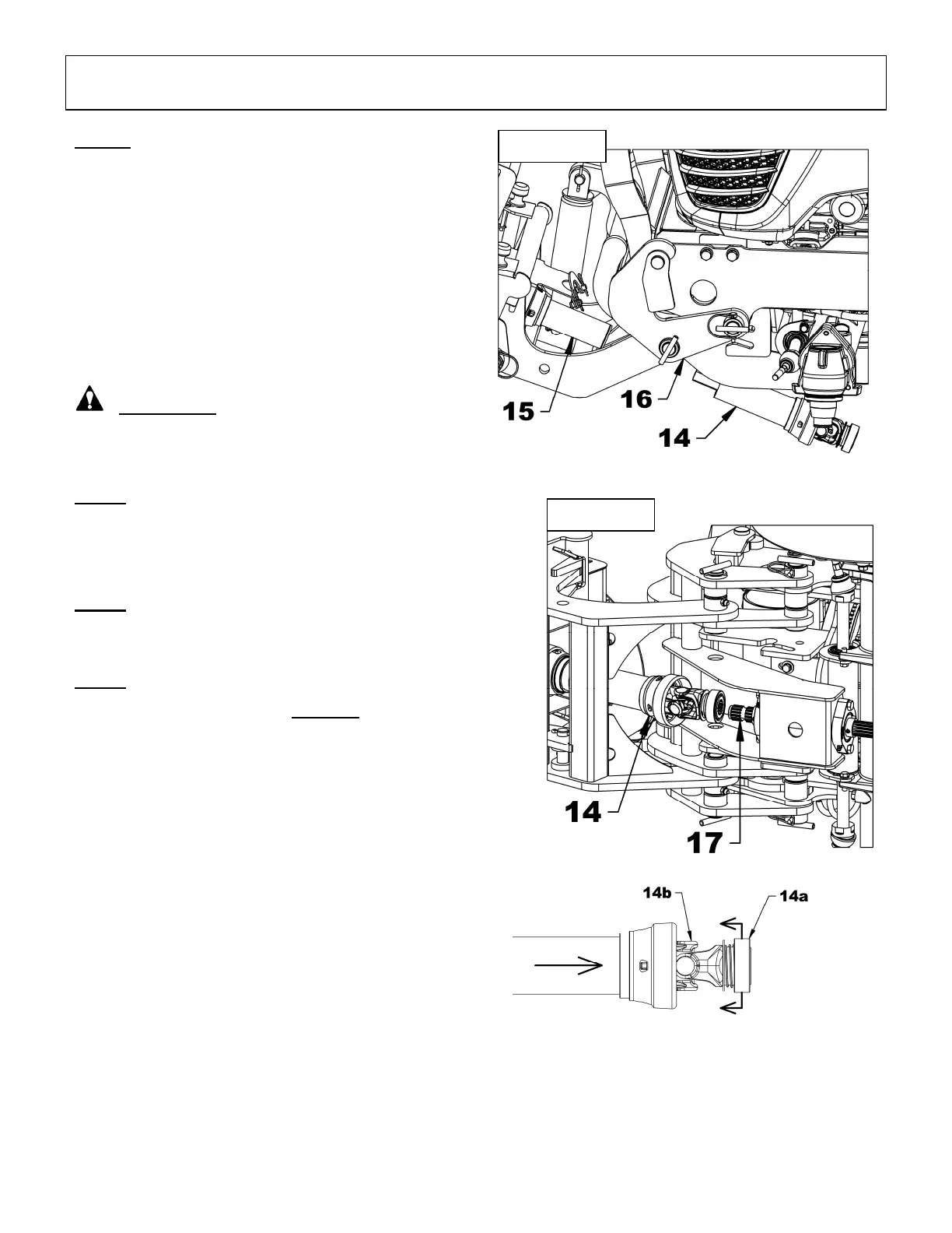
Figures 10-11: Place the male driveline (item 14)
under the subframe (item 16) and insert in the
equipment female driveline (item 15). Attach the
male driveline (item 14) to the subframe output
shaft (item 17). To do so, disengage the locking
collar (item 14a) by pulling it back and push on the
yoke (item 14b) to connect the driveline to the
subframe output shaft (item 17). Release the yoke
and make sure the locking collar is back in its
proper position. Pull and push on driveline
(item 14) to make sure it's securely locked.
WARNING: To avoid serious injury or
death: Make sure that the quick connect yoke
is securely locked in place. A "click" must be
heard.
Step 6
Install the specific items for each equipment.
Example : manual rotation of the chute of a
snowblower.
Step 7
With the hydraulic control lever lower the
equipment to the ground.
Step 8
Adjust the engine speed to low rpm and engage
the PTO. Increase engine speed gradually until it
is at full throttle before beginning to use the
equipment.
Figure 10
Figure 11


 To Next Page