14
2.7 Control Panel
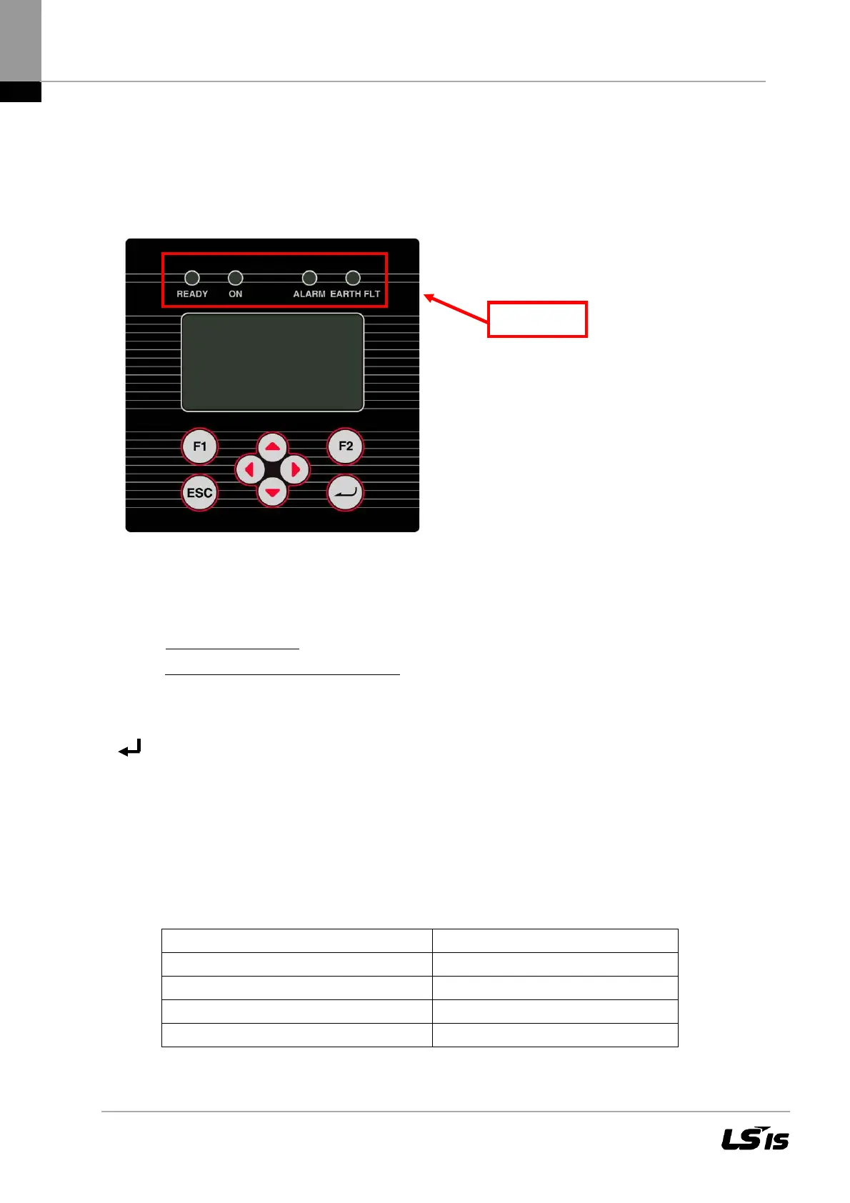
The graphical user interface which is integrated on the front of the device and comprises 128 x 64
pixels can be used to display the development of interesting data, such as the feed power. The
parameters required are selected and entered on the 8-key control panel. The control panel is illu-
minated on pressing a key and turns dark automatically.
Figure 6 Control panel
F1: Display the menu.
◄►: Function in the menu
: jump to the first or last menu item.
Function while parameters are edited
: digit to the left, digit to the right (decade jump).
▲▼: Select the menu.
ESC: Acknowledge failures and delete entries.
: Confirm the selected menu and entered data.
2.8 Internal Data Logger
The LSPV inverter features an internal data logger that allows measured values to be simultane-
ously recorded in the form of parameters. The data logger is implemented as a ring buffer. If this
buffer is full, the oldest data is overwritten. With the default setting on delivery, the data logger logs
16 measuring channels.
Recording cycle Storage time
1 minute 6 months
2 minutes 12 months
5 minutes 2,5 years
10 minutes 5 years
Status LED

 Loading...

