18
CAUTION
Any failure to observe these requirements may result in a malfunction
of the device or may even cause severe personal injuries through
crushing, shearing, cutting, striking, or fire!
When designing the attachment of the wall-mounting plate, take the weight of the LSPV inverter of
40 kg into account.
• Mounting the wall bracket: Use the wall bracket to mark the positions of the holes to be
drilled. Attach the mounting plate to the wall with the outer holes.
• Insert the upper edge of the cooler into the recess of the device holder. Push the LSPV
inverter upwards until it stops and place the lower edge of the cooler onto the wall holder.
Ensure that the rib profile is locked behind the nuts. Finally secure the LSPV inverter in
these nuts using the enclosed screws (M5x20). As an alternative, you can also use a
padlock (shackle 4 mm in diameter) as anti-theft protection. The design of the wall
bracket ensures that the LSPV inverter is automatically centered in this bracket.
CAUTION
Avoid any load on the edge of the cover while mounting the device!
Do not use the cover to hold the device!
Only use the four holding grips to move the device!
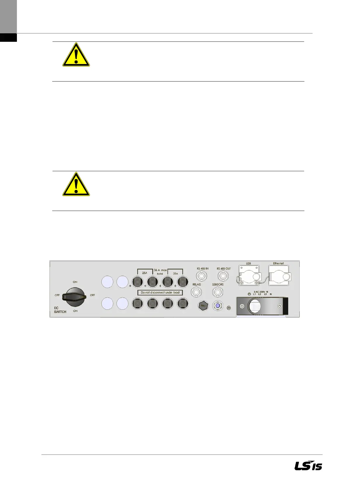
3.6 Connectors on the Device
The following figure shows the connectors of the LSPV inverter on its bottom side.
Figure 10 Device connectors
The LSPV inverter is provided with the following connectors, as seen from left to right:
• 4/6 pairs of PV generator connectors
• SENSORS (connection: radiation and temperature sensors)
• RELAIS 230 V/2 A AC (fault message)
• RS 485 connectors (IN and OUT)
• USB and Ethernet interface ports
• Power connection

 Loading...

