15
3 Installation
3.1 Unpacking the Device
The inverters are loaded at their head and packed upside down facilitate transport. You will there-
fore see the bottom side of the device (connectors) after having opened the package. Take the
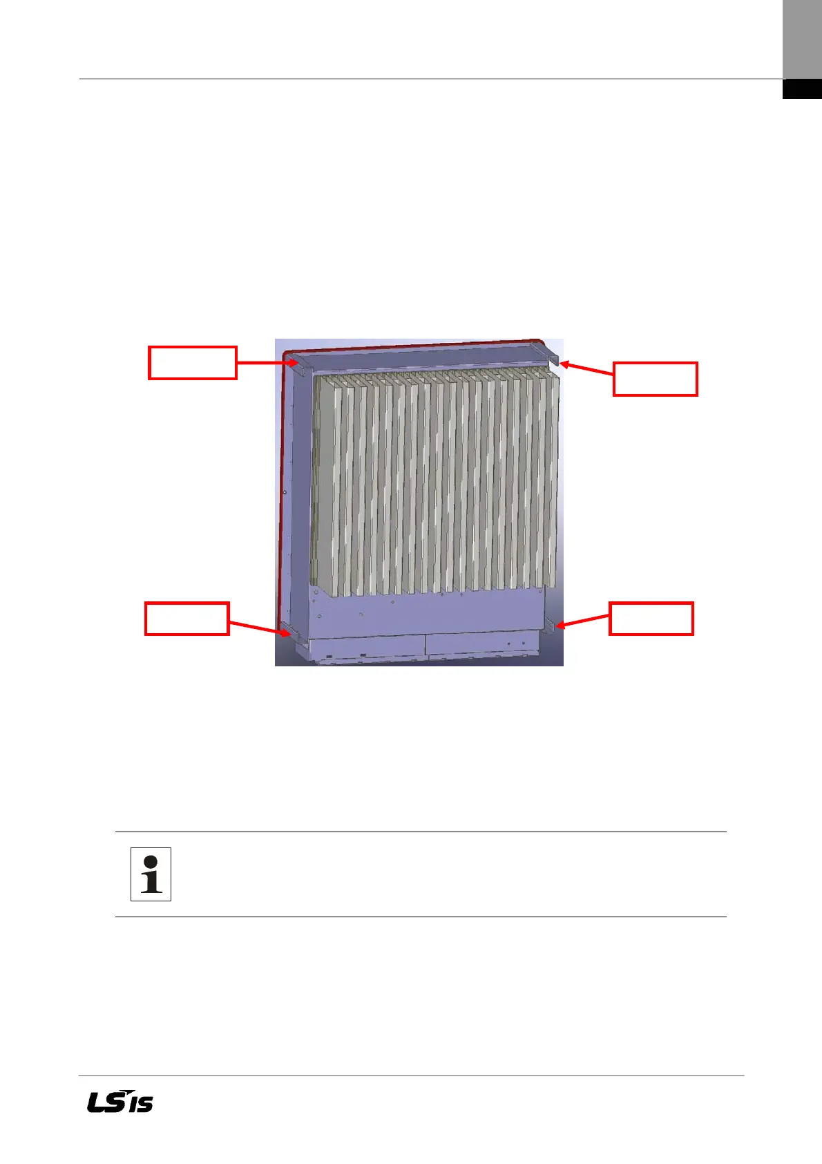
device at the two holding grips that are visible on the side and remove it from the packaging. When
being unpacked, the device keeps the packaging grid locked in place on its housing. The packag-
ing grid can be used to deposit the device on the floor. This prevents the cover from being dam-
aged.
Figure 7 Rear panel of LSPV inverter 010K to 020K
3.2 Assembly Site Requirements
The LSPV inverter is provided with mere convection cooling and is therefore designed for attach-
ment to a vertical wall. The device is attached by means of a self-centering wall-mounting plate.
Note: To prevent accidents when installing and servicing, free and safe
access to the devices must be ensured.
• The assembly site must be shaded.
• The device may only be mounted in a vertical position.
• This requires a firm wall or metal structure. Do not attach the device to wooden
boards, wallboards or the like! Please note that the device weighs 40 kg. The load-
carrying capacity of the wall and the attachment of the device(s) must be designed
based on this weight (pertinent construction rules must be observed)!
Holding grip
Holding grip Holding grip
Holding grip

 Loading...

