11
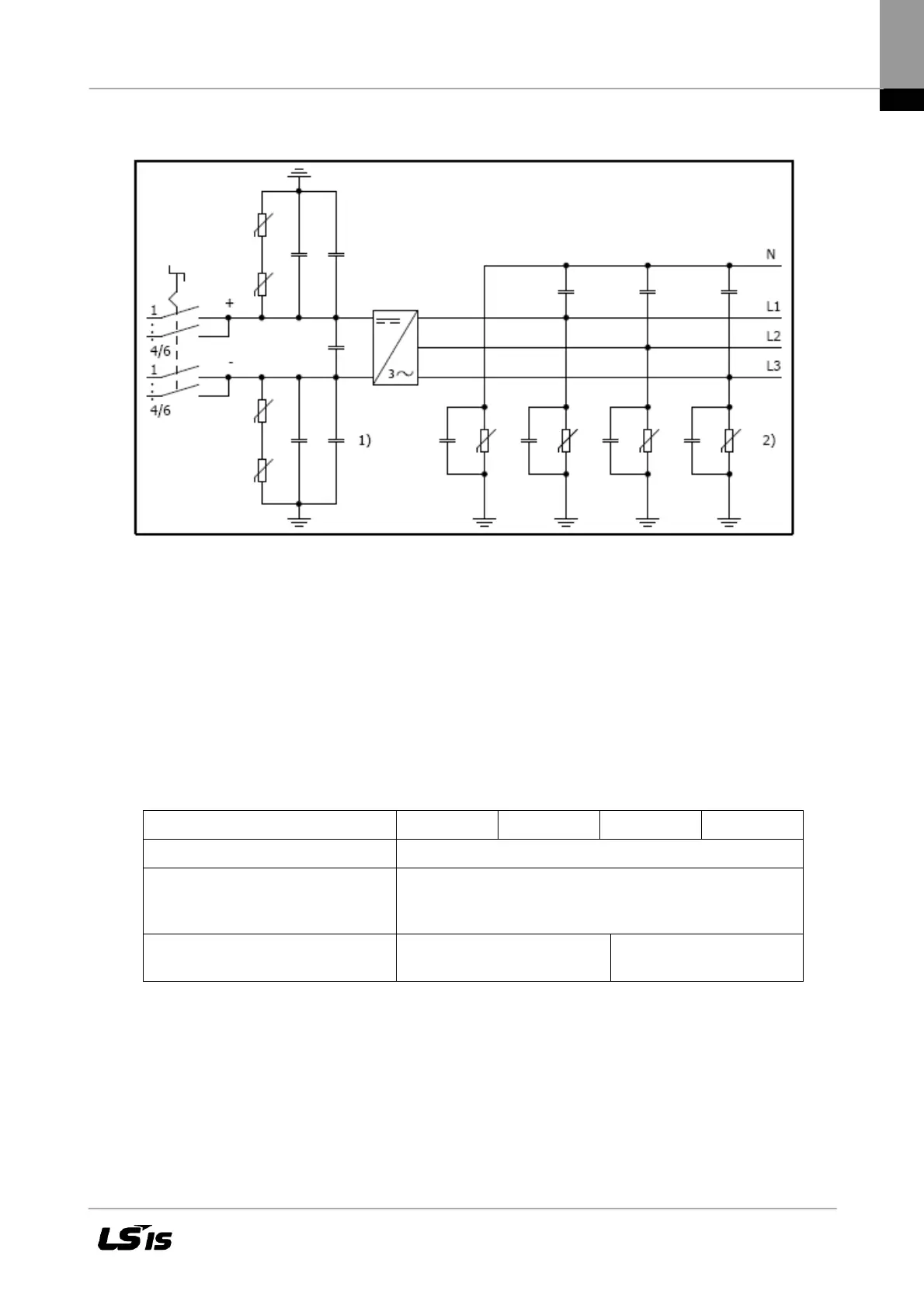
2.4 Block Diagram of the LSPV inverter 010K to 020K
Figure 3 Block diagram of the LSPV inverter 010K to 020K
1) DC overvoltage protection, type 3
2) AC overvoltage protection, type 3
2.5 Solar Inverter DC Connector
The PV generator may not exceed the following operational characteristics under any circum-
stances!
Device type 010K 013K 017K 020K
Max. DC voltage at each input 1000 V
Max. current for each DC input pair
(010K to 013K ) and DC input trip-
let (017K to 020K), respectively
25 A
Max. DC current at the input
across all connections
36 A 41A
To keep the maximum current allowed of 25A at the DC Circuit breaker contacts, observe the fol-
lowing input assignments.
The power of the PV generator must be uniformly distributed over all 4 inputs (010K
to 013K) or 6 inputs (017K to 020K). The maximum DC current of 36 A /41A may not be exceeded.

 Loading...

