24
3.14 Interface Port RS485
RS485 OUT RS485 IN
Pin 1 Bus termination+ Pin 1 Reference +
Pin 2 RS485+ OUT Pin 2 RS485+ IN
Pin 3 RS485- OUT Pin 3 RS485- IN
Pin 4 Bus termination – Pin 4 Reference –
* Bus termination (wire jumper)
• RS485: Connector contained in the enclosed bag (order number 0030532).
The RS485 interface supports the USS protocol (Universal Serial interface protocol) which can be
used for transmission of data, for example, to a data logger of a remote monitoring system.
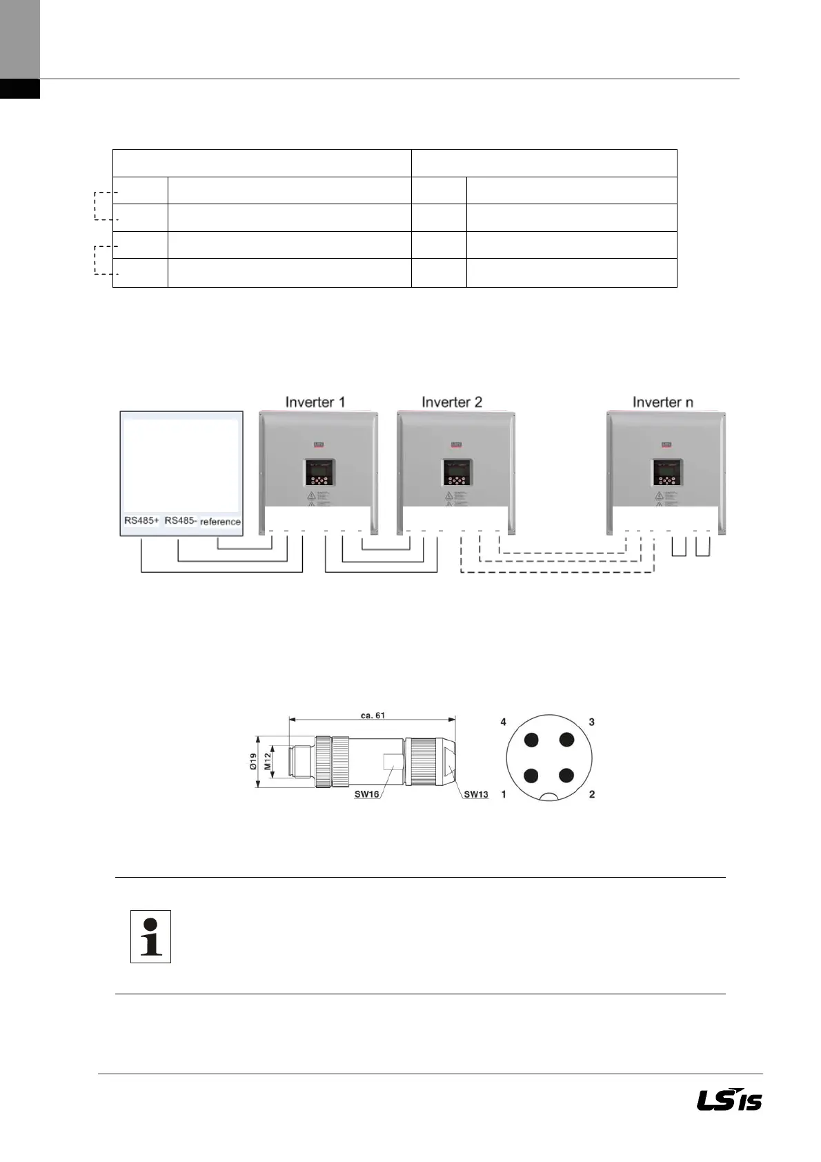
Figure 13 Standard interface connection
When using this interface, please note that each device using the bus requires a unique address.
Bus termination is made by means of wire bridges on X14 to the last bus user (inverter “n“).
● 2 X Plugs contained in the enclosed bag, 1 X RS485 (IN), 1 X RS485 (OUT).
Figure 14 Connector M12 x 1 straight, shielded; pole arrangement: male M12, 4 pins,
A-coded, view of male connector side
Note: The RS485 interface connecting cables must be shielded.
The shield must be applied according to the plug manufacturer's
specifications. The outer diameter of the connecting cable can be
max. 8mm.
ref., X15 / IN , X14 / OUT ,
ref.
4 3 2 2 3 4
ref.,
X15
/
IN ,
X14 / OUT ,
ref.
4 3 2 2 3 4
ref., X15 / IN , X14 / OUT
4 3 2 1 2 3 4
PMU
Data Logger
Remote Monitoring
System
*

 Loading...

