22
3.10 Grounding
CAUTION
Risk of electric shock!
The LSPV inverter
must be connected to the ground stud. Otherwise, a
voltage gradient may develop, which may result in electric shock!
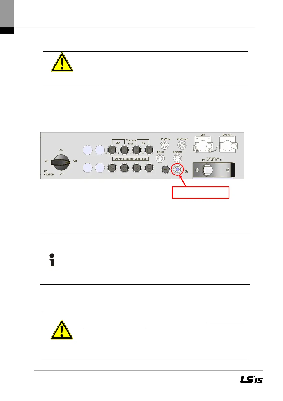
The LSPV inverter features a threaded bolt below the power supply port on the connection side for
additional grounding. Grounding is intended to ensure optimum overvoltage protection. That is why
the ground wire cross-section must be chosen in excess of the cross-section of the power supply
line by a factor of one (at least 10 mm²). In addition, ensure that the ground wire is placed as far
away from and not directly in parallel to the power supply line.
Figure 12 Grounding bolt
3.11 Residual Current Protective Device
Since February 2009, RCDs (residual current protective devices) have been prescribed for recep-
tacle circuits of up to 20 A in interior rooms and of up to 32 A in outside areas which are used by
electrotechnical non-professionals.
Note: The photovoltaic power supply inverters without transformers meet
the fault protection requirements according to DIN VDE 0100-712,
IEC 60364-7-712:2002 and CEI 64-8/7 and can be operated with a
type A residual-current circuit breaker without any functional
impairment of the protection or the inverter.
The rated leakage current should be at least 100 mA per inverter.
3.12 PV- Generator DC Connection
CAUTION
Before connecting the PV strings, connect the inverter to the power supply
network and to the ground bolt to ensure that the device is safely connected
to the protective conductor.
Connect the PV strings to the LSPV inverter only in the de-energized state,
optimally in the dark because that is when the PV strings are inactive.
The protective conductor must be connected to the housing separately from
and in addition to the power supply connection.
Grounding bolt PE

 Loading...

