Chapter 13 Installation and Wiring
13 3
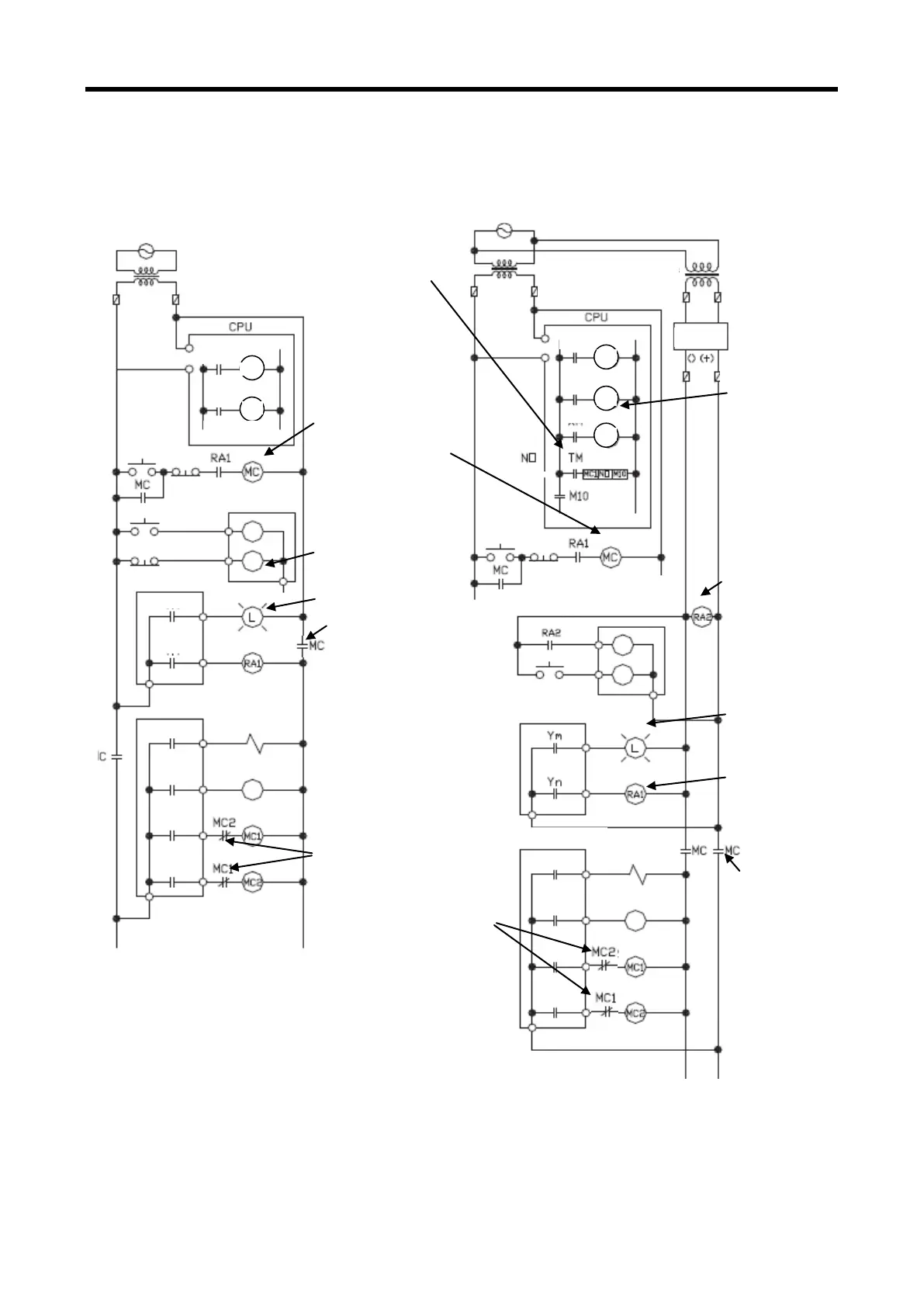
13.1.1 Fail safe circuit
(1) example of system design (In case of not using ERR contact point of power module)
In case of AC In case of AC . DC
Check direct
current
Signal input
Timer setting
which DC input
signal is
configured.
Output for warning
(Lamp or buzzer)
Power off to output
device
Output for warning
(Lamp or buzzer)
Power Off to
output device
Configure part that
lead opposite operation
or breakdown such as
interlock circuit
forward, reverse
revolution by external
interlock circuit
(Emergency
stop,
stop by limit
switch)
Emergency stop,
Stop by limit
Start sequence of power
In case of AC
(1) Turn on power
(2) Run CPU.
(3) Turn on start switch
(4) Output device runs by program through
magnetic contactor (MC) [On]
Start sequence of power
In case of AC DC
(1) Run CPU after power is on
(2) Turn on RA2 as DC power on
(3) Turn on timer after DC power is stable.
(4) Turn on start switch
(5) Output device runs by program through
magnetic contactor (MC) [On]
PLC RUN output
Start available as
RA1
 Loading...