43
current to start, and a small starting current may cause its failure to start
normally. When the temperature drops below zero, the motor will require
greater input power within a certain period of time.
The higher the power supply voltage and the stronger the discharge capacity,
the more severe the impact on the lidar. Before mounting the lidar, please
contact our technical support personnel for power supply environment
evaluation to avoid damage.
For DC power supply, it is recommended to use wires of between 18 AWG and
26 AWG. The calculation formula of the voltage drop ∆𝑈 is shown below:
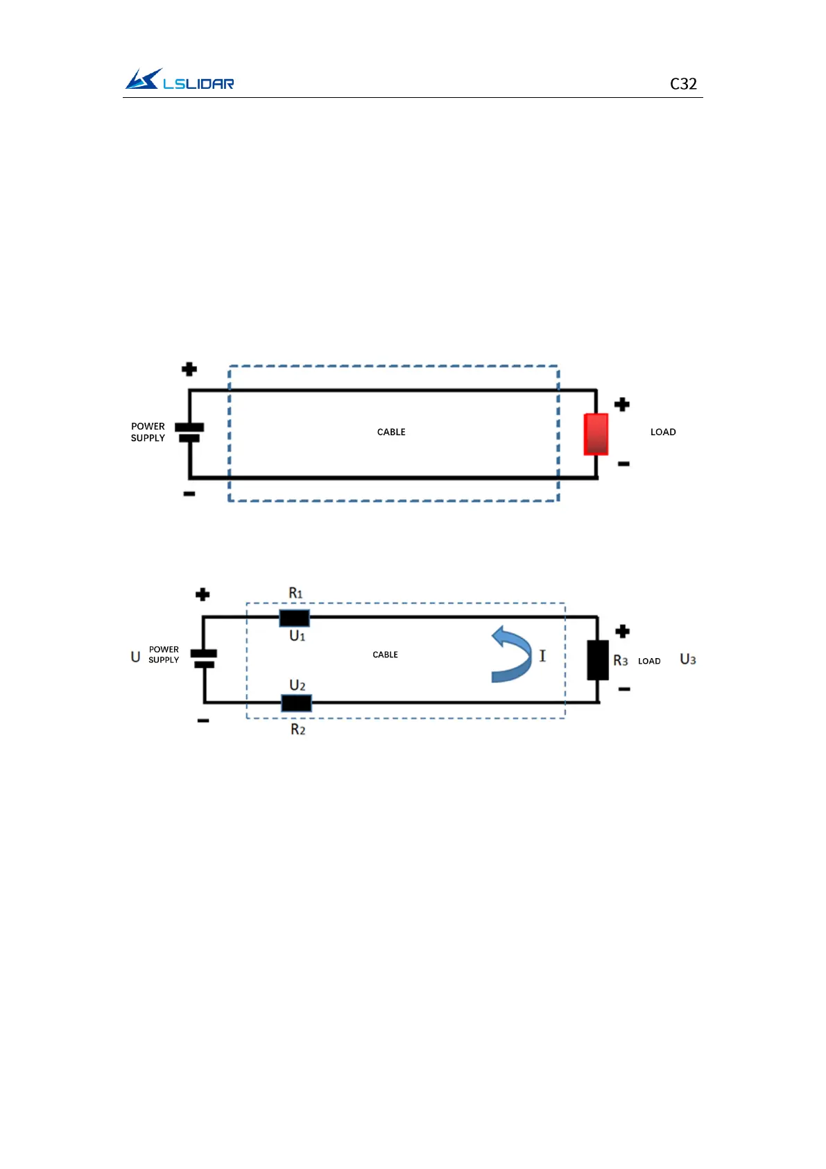
Equivalent Circuit:
U = U1 + U2 + U3
Voltage Drop: ∆𝑈=U1 + U2=I ∗
(
R1 + R2
)
=2 ∗ IR1=I ∗ ρ ∗ L ∗ 2/S
It can be seen from the above formula that there are four factors that cause the
voltage drop on the cable, namely: working current I, density ρ, length L, and
conductor cross-sectional area S. When the lidar and wire are determined, then
these four variables are all known quantities, and the voltage drop ΔU can be
calculated.
Since it is often impossible to carry out such detailed calculations on the
construction site, we will give some suggestions based on our experience. For
the use environment that requires long-distance power supply, if the length of
the extension cable is within 5 meters, the power supply voltage can be 12VDC;
5~10m, no less than 19V; 10~50m, no less than 24V; more than 50 meters, it is