The smaller the ripple, the better. Too
much ripple will cause irreversible
damage to the hardware.
12 V power supply at 10 Hz
recommended. When scanning at 20
Hz, the lidar power consumption will
also be higher than the recommended
value.
The period is 1 second, the
recommended pulse width is more
than 1 ms.
RS232 level, baud rate 9600 bps,
compatible with TTL and RS232 level.
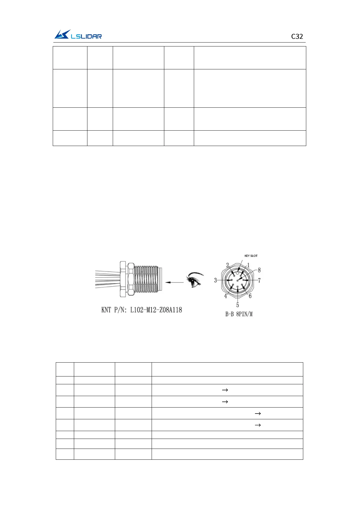
2.2 Connectors
Male connector on the lidar base
There is an 8-pin male connector on the side of the C32 lidar base, and the wires
can be led out by using an extension cable with a female socket, an adapter cable
or an interface box. The cable connector model on the side of the C32 lidar base
is L102-M12-Z08A118. You can use an extension cable with a female connector
or an adapter cable to lead out the wires to achieve system power supply and
data communication. The lidar supports GPS timing function, and the cable
connector is shown in Figure 2.1 below.
Figure 2.1 Cable Connector on the Lidar Base
The definition of the 8-pin male connector is shown in the table below.
Table 2.2 Pin Definition of the 8-pin male connector
Ethernet data flow: lidar external devices
Ethernet data flow: lidar external devices
Ethernet data flow: external devices lidar
Ethernet data flow: external devices lidar
GPS Sync Pulse/External Sync Pulse
GPS latitude & longitude, hour/minute/second