3
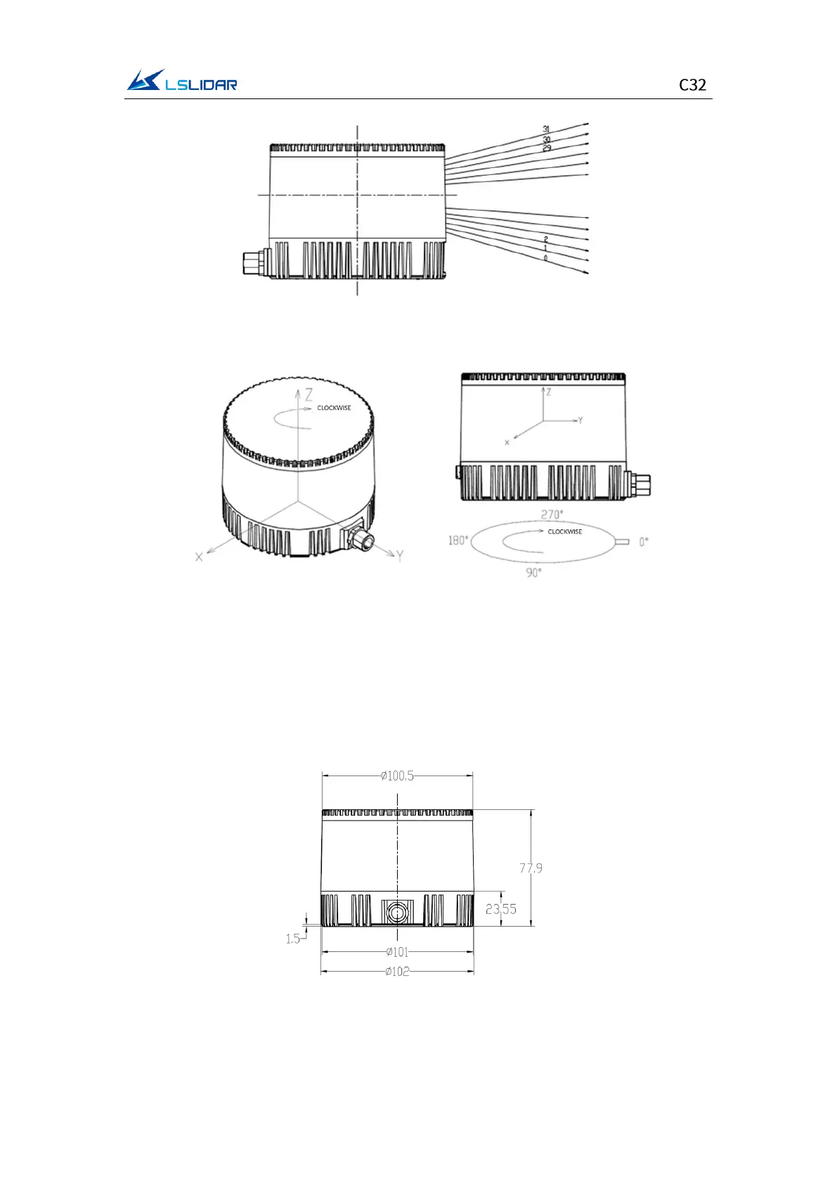
Figure 1.2 Laser Beam Distribution
Figure 1.3 Coordinates & Scanning Direction
Note: As shown above, the cable connector of the lidar marks its zero-angle
position. (It can be changed to the opposite of the cable connector in the
Windows Client software.) When the laser beams pass through the position of
the cable connector, the azimuth angle of the corresponding data block in the
output UDP packet is 0°.
Figure 1.4 C32 Dimensions