23
Lift and install the camera module
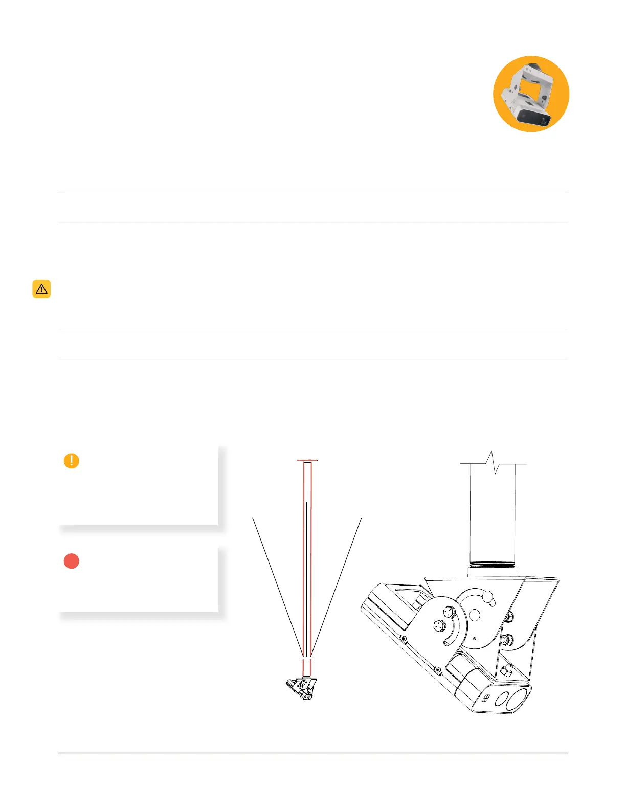
Stabilization cables systems (to be used on all pipes longer than 24” [60 cm])
Secure the camera module using the ceiling plate and a DN 40 (1 1/2”-11.5 NPS) threaded pipe (length to be
determined by the ceiling height; the bottom of the camera should be at 18’ [5,5 m] from ground).
Use a self-drilling screw at the ceiling plate to block any pipe rotation.
Connect power cords (1 connector) into the light module power strip.
Install the ring on the pipe at 1/3 of the length of the pipe from the camera.
Install all 3 metal cables at 120 degrees angle towards the structure in the ceiling.
Stretch rmly the 3 cables with the turnbuckles until the pipe is stabilized at 90 degrees from the ceiling in
all directions and rmly holds in place.
02
02
03
03
INSTALLATION RIGGING -
CAMERA MODULE (E)
01
01
Note: The camera
rotation bracket will
be locked later during
calibration.
Ceiling mount with a DN
40 (1 1/2”-11.5 NPS)
threaded pipe
A
A A